Removing IHS along with intels non-solder epoxy die attach and replacing with less effective user tim with questionable contact is not evidence of anything. Just shows removing 1 layer, but replacing with less effective die attach specs is a crapshoot. Pk1 even though high bulk thermal conductance, has no chance of competing with intels non-solder die attach in terms of voidless, no air pockets, contact resistance, bondline thickness.
Intel via third party already said it is tim difference + thermal density increase, but should be obvious anyways.
You can mathematically figure out the gradient across tim. At 120W load, the gradient across solder tim would be 1.2C, 120W x .0098C/W for solder specs listed in white paper linked below and see attached pic/chart. At 120W load of modern cpu, using best non-solder die attach specs from places that sell non-solder die attaches, gradient would be 5-8X that of solder or 6-9C increase in gradient over non-solder. It defies physics to argue tim change does not increase temps to some degree.
And changing the critical density from 32nm to 22nm, means thermal density increases significantly, so core temps will increase significantly.
The only question is how much of each contributes.
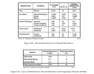
You can see from white paper pic, that paste on this cpu causes a 6C gradient across silver paste tim. Replace that with specs listed chart above for solder tim, and get less than 1C for solder. And that is with 20W. Modern non-solder die attaches have improved, but still lag 5-8X behind c/w of solder.
http://smithsonianchips.si.edu/ice/cd/PKG_BK/CHAPT_06.PDF