• Welcome to Overclockers Forums! Join us to reply in threads, receive reduced ads, and to customize your site experience!

4 pin fan PWM signal to 3 pin fan

Overclockers is supported by our readers. When you click a link to make a purchase, we may earn a commission. Learn More.

T=K

Registered
Joined
Jul 18, 2011
So I imagine everyone in this forum who is interested in fan controllers has come across Bing's PWM controller for 4 pin fans.

My thought is that it would be great to have a small circuit that could be bolted on to the output of his controller to turn the 0-5V PWM signal into an average analog voltage between 0 and 12 volts (As opposed to a 0-12V PWM signal directly on the power rail of the fan) while still supplying enough power to drive a few fans (At least 20W, ideally well over 30W)

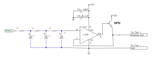
So idea #1 is to use a low pass filter on the PWM signal and a high power op amp to scale the voltage up to the right levels The one I'm using is 3A, although there are even higher power ones for more money if you need the extra juice. The one I used in this circuit is linked. It is $1.71 from digikey. (A 5amp alternative, although some extra wiring is required).

So without further ado, hopefully this one makes much more sense. I send the output of the low pass filter into the + terminal of the OP AMP, and then the - terminal is hooked up as a non-inverting OP AMP with a gain of ~2.4, which is also 12/5.

PWM%20Circuit%20v2.png


Although according to Bing, there may be an issue with not being able to reach the full 12V with this circuit, so I'll also be looking into additional options.
 
I don't think I understand what you're trying to do. Why would you rather control voltage to control a fan rather than use pwm? Why not just make a 12v pwn controller? I don't see the point of controlling 0-12v, I don't think most fans will be very responsive to voltage change below a certain point. If anything it would not be a very efficient method.

You wouldn't much more than a 555 and a fet to do pwm. You would really just be adding a fet to Bing's setup. The controller would run the fet which would control the 12v for the fan.
 
It has been discussed previously that trying to PWM a fan that is not made to be PWM controlled can cause some problems, so unfortunately I don't think just slapping a FET at the end of the circuit will solve the problem.
What I'm looking into now is called a "Buck Converter". Basically a combination inductor and capacitor circuit to smooth out a rippled signal. Found a guide on component selection, but still not fully grasping the calculations yet.
 
Last edited:
Looks fine. But the traditional approach here is to just use a rheostat on the 12v line. Considerably less complex, though there may be more heat dissipation issues with that approach depending on how much current you run through it.

If you want an active solution, why not just use a single MOSFET in a buffer configuration with a variable resistor to bias the output? It won't have quite the rail-to-rail performance some opamps might have, but it's also a lot simpler. Judging from the spec sheet of the opamp you linked, it's not going to do particularly well rail-to-rail either.

Finally, I'm confused about why we would want to take 12v, convert it to PWM, then convert it back to analog.

*Edit*
so unfortunately I don't think just slapping a FET at the end of the circuit will solve the problem.
The part of the circuit that's doing the real PWM-to-analog conversion here is that lowpass filter you have on the positive opamp input. So I think penguin's right - you don't need the fancy feedback qualities of the opamp, you just need to lowpass the PWM signal and bias a buffer with it, in which case your generic FET would work fine.
 
Finally, I'm confused about why we would want to take 12v, convert it to PWM, then convert it back to analog.

*Edit*

The part of the circuit that's doing the real PWM-to-analog conversion here is that lowpass filter you have on the positive opamp input. So I think penguin's right - you don't need the fancy feedback qualities of the opamp, you just need to lowpass the PWM signal and bias a buffer with it, in which case your generic FET would work fine.

So for your first question, it's mainly so that it can also accept the PWM signal from the motherboard. Once I get this circuit nailed down it will be easy to slot in a selector switch and possibly a digital buffer.

As for the second, that does sound much more simple, I'm just trying to remember all that I used to know about MOSFETs, because from what I remember it would for the most part amplify the circuit all the way to 12V instead of having a nice linear response. I could certainly be wrong though.

TK
 
As for the second, that does sound much more simple, I'm just trying to remember all that I used to know about MOSFETs, because from what I remember it would for the most part amplify the circuit all the way to 12V instead of having a nice linear response. I could certainly be wrong though.
If biased as a buffer, the general rule is that you'll see a ~0.7v drop from the gate voltage to the output voltage - the same sort of drop you'd see across a diode. The response is extremely linear within the region of operation: output = input - 0.7v.

http://en.wikipedia.org/wiki/Buffer_amplifier
 
I suppose I do overthink things sometimes. So would something like this fit the bill?

PWM%20COntroller%20V3.png
 
Yeah, probably. Easier to source higher currents that way too, I would guess. You're doing a SPICE simulation?
 
This is sort of a round about way of doing things. If you want a buck converter, you can buy a single IC that generates the PWM and usually only needs two or three external components. They use this on 3-pin fan controllers that don't use linear regulators.

If you use an RC lowpass with an op-amp buffer, but you'll have to be careful with picking the values. I think you'll see the charge/discharge cycles at the output though (a simulation should show this if its the case). Also this won't give you linear control. The lower range of tweaking will give you huge changes in output voltage because of the RC exponential.

For controlling 3-pin fans with pwm from a mobo, I think your best bet is to do a buck converter. It gives you linear voltage control, and while the range isn't amazing, it should give you a diode drop below supply (~11.7 if you use a schottky) down to a couple volts.

The challenge here is interfacing the mobo pwm with the buck converter. I believe mobo pwm is an active low signal whereas you need active high for all (or at least most) buck converters. Its also at 12V so you might have to use a beefier mosfet than whats offered in the integrated solutions. The other issue you may run into is pwm frequency. I think mobo pwm should be fast enough but Im not sure. It might not be as efficient as the higher frequency pwm's, but since when do we care about that :D

I was looking into this, but it looks like at 25kHz I'll need at least a 150uH inductor in the circuit, and one that can handle 3-4 amps is also $3-$4, so I think that a MOSFET is much cheaper, at <$1 (for instance this one which can handle >100W).

To be honest, not really sure hoe to do a spice sim. Looks like most versions cost money, and the free ones are really confusing. Any pointers to a good free one?

Thanks,
TK
 
No, unless PSPICE is free. That's what it looked like you were using from the picture.
 
I was looking into this, but it looks like at 25kHz I'll need at least a 150uH inductor in the circuit, and one that can handle 3-4 amps is also $3-$4, so I think that a MOSFET is much cheaper, at <$1 (for instance this one which can handle >100W).

To be honest, not really sure hoe to do a spice sim. Looks like most versions cost money, and the free ones are really confusing. Any pointers to a good free one?

Thanks,
TK

You should still be able to get the pspice student version for free online. It's very simple and limits the number of components you can use but for this purpose it should be more than enough. The challenge will be to find models. There are also some open source versions, but I can't remember the names. You should be able to find them though.

So that MOSFET you linked will not work for what you're trying to do. That's a Power MOSFET (you can tell from the way they write the specs). It's a completely different structure from that used in analog/digital integrated circuit design and isnt intended to work as an amplifier. These MOSFETs are generally used as electronic switches, hence the extremely high voltage/current tolerances.

Also, the last circuit diagram you posted has it in a high-side configuration. In order for that to work, your voltage generally needs to be above the supply rail, i.e. above 12V. It has a threshold of 5V, meaning it wont even conduct current until that point. But even at 5V, it conducts ~100mA, giving you a pretty decent voltage drop across that resistor. So you'll need to go higher. At 6V, it conducts ~10A, your output would basically be 12V, and that gives you negative Vgs. You get the idea. Usually in high side configurations a charge pump is used to generate voltages above the supply rail. That's not what you want.

If you do want to use an amplifier transistor, use a BJT. Theyre also dirt cheap, but will work as an amplifier. You'd want an NPN, and you should be able to use this as an emitter follower as you're intending to. But this still might not be as accurate since you're depending on the linearity of the transistor and you also have the base current to deal with.

I think your best bet is to basically create your own LDO. You use an op amp and the npn bjt in emitter follower. The feedback and op amp gain will give you a much better output, and you can use a much cheaper op amp since the current is fed through the bjt.

I'm curious to see if this works. Your max voltage is about 11.3V (12-0.7). Minimum is all the way down to 0.
 

Attachments

  • Untitled.png
    Untitled.png
    13.8 KB · Views: 9,523
Last edited:
So I finally found a version of spice that is free, LTSpice. It's made by Linear Technologies and comes with models for all their products, which is quite convenient. You can get it here http://www.linear.com/designtools/software/

So back to my circuit. I modified the orignial a bit, and went back to a combination of a low pass filter to a non-inverting op amp to the LT1083 adjustable voltage regulator.

So here is what the circuit looks like currently:

PWM%20COntroller%20V4.png

R5 and C5 should provide a ~.75 second burst of full power to the fans on initial turn on until leveling to whatever the PWM in is.

I set up the DC input as a 0-5 volt sine wave to show the output calculated by Spice. The blue line is the DC supply, the green line is the output. It only gets up to 11 volts, but I think that should be plenty of juice. I guess it sounds better if I just say that this one goes to 11!

PWM%20COntroller%20V4%20Output.png
 
I'm curious- what does your output voltage look like when you give it a square wave input?
 
PWM%20COntroller%20V4%20Output%20Square.png


I reversed the blue and green this time by mistake, but I imagine you get the idea
 
I'm a little confused. What are the plots here? PWM In and Analog Voltage Out?

I'm curious to see how much the ripple is on the output and how the duty cycle on the PWM actually effects the output voltage
 
No, the voltage in after the low pass filter, I've tried putting in a square wave in spice to make sure it comes out correctly, but it makes the simulation take forever to have a voltage source running at 25kHz. So I bypass the filter with a voltage source to simulate the output

Edit: So the input on pin 3 of the Op Amp is V(n005) and the voltage of the output is V(n002)
 
No, the voltage in after the low pass filter, I've tried putting in a square wave in spice to make sure it comes out correctly, but it makes the simulation take forever to have a voltage source running at 25kHz. So I bypass the filter with a voltage source to simulate the output


That's weird. A simple transient simulation like that shouldn't take very long at all. I'm curious to see how that filter works out because you'll need a really sharp cutoff to get rid of those harmonics and get a nice flat voltage.
 
That's weird. A simple transient simulation like that shouldn't take very long at all. I'm curious to see how that filter works out because you'll need a really sharp cutoff to get rid of those harmonics and get a nice flat voltage.
Yeah. Tuning that filter is going to be a real pain.
 
Back