• Welcome to Overclockers Forums! Join us to reply in threads, receive reduced ads, and to customize your site experience!

4 pin fan PWM signal to 3 pin fan

Overclockers is supported by our readers. When you click a link to make a purchase, we may earn a commission. Learn More.
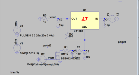
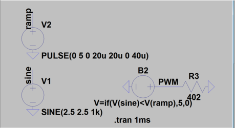
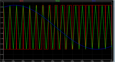
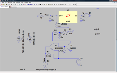
Ah. So the problem is that your first simulation is actually correct. You should be using "if sine > ramp". The reason it seems backwards is because that's actually how it would operate. The mosfet is essentialy inverting your PWM signal. When the PWM is high, the input to the RC filter is held low, giving you the low output at 100% duty cycle. When the PWM is low the mosfet is off. So basically you're flipping your PWM signal. If you get rid of the mosfet, and connect the PWM source directly to the resistor, I think you'll get your expected response. Problem is this won't actually work... I'll try to think of something.

Edit: Ok, so what you can do is add another mosfet to invert the signal a second time getting you the overall correct response. Try this: add a resistor (4.7k) from PWM to 5V. This one isn't needed for sim, but will be needed if you build it. Connect PWM to the gate of a p-channel mosfet. The source of this mosfet is connected to 5V, and the drain is connected to another 4.7k resistor to ground. That drain is also connected to the gate of the mosfet you already have in there. This should make it such that higher duty cycle = higher voltage.

Now the only thing that could potentially be an issue is what looks to be an exponential relationship between duty cycle and output voltage. The solution I came up with is slightly more complicated than what you've got, but its definitely doable. If you're interested let me know.
 
Last edited:
Ah, was unaware of the inversion. Well since I'm gonna be changing things I'm gonna swap the mosfets out and just use transistors. No need for the fets.
 
Penguin, here a quick & dirty small circuit in easing you to create an easy to modulate pwm signal that is suitable in your work there, though it might add the ltspice simulation time, but I think its worth it especially you want to test the whole range and also on different conditions of pwm's duty cycle for your converter circuit.

Just copy & paste the below boxed text into notepad, and save into <whateverfilenameyoulike>.ASC file and open it with ltspice.

Code:
Version 4
SHEET 1 1724 920
WIRE -288 -80 -688 -80
WIRE -240 -80 -288 -80
WIRE -112 -80 -240 -80
WIRE -16 -80 -112 -80
WIRE 320 -80 -16 -80
WIRE -688 -64 -688 -80
WIRE -240 -48 -240 -80
WIRE -16 -48 -16 -80
WIRE -560 32 -592 32
WIRE -288 32 -288 -80
WIRE -288 32 -336 32
WIRE -48 32 -96 32
WIRE -688 48 -688 16
WIRE 80 48 48 48
WIRE 320 48 320 -80
WIRE 320 48 304 48
WIRE -112 64 -112 -80
WIRE -96 64 -96 32
WIRE -560 96 -592 96
WIRE -240 96 -240 32
WIRE -240 96 -336 96
WIRE -144 96 -160 96
WIRE -16 112 -16 32
WIRE -16 112 -64 112
WIRE 80 112 -16 112
WIRE -144 128 -176 128
WIRE -240 144 -240 96
WIRE -288 160 -336 160
WIRE 80 176 64 176
WIRE 320 176 304 176
WIRE -96 192 -96 160
WIRE -48 192 -48 32
WIRE -48 192 -96 192
WIRE -128 208 -128 160
WIRE -112 208 -112 160
WIRE -112 208 -128 208
WIRE -128 256 -128 208
WIRE -592 288 -592 96
WIRE -288 288 -288 160
WIRE -288 288 -592 288
WIRE -240 288 -240 224
WIRE -240 288 -288 288
WIRE -176 288 -176 128
WIRE -176 288 -240 288
WIRE -16 304 -16 112
WIRE 320 304 320 176
WIRE 320 304 -16 304
WIRE -240 320 -240 288
WIRE 64 336 64 176
WIRE 400 336 64 336
WIRE -240 400 -240 384
WIRE -368 448 -512 448
WIRE -160 448 -160 96
WIRE -160 448 -368 448
WIRE -512 512 -512 448
WIRE -512 624 -512 592
FLAG -240 400 0
FLAG -592 32 0
FLAG -128 256 0
FLAG 400 336 PWM
IOPIN 400 336 Out
FLAG 48 48 0
FLAG -688 48 0
FLAG -368 448 DutyCycle
FLAG -512 624 0
SYMBOL Misc\\NE555 192 144 R0
SYMATTR InstName U3
SYMBOL res -256 -64 R0
SYMATTR InstName R1
SYMATTR Value 10K
SYMBOL res -256 128 R0
SYMATTR InstName R2
SYMATTR Value 47K
SYMBOL cap -256 320 R0
SYMATTR InstName C1
SYMATTR Value 550pF
SYMBOL res -32 -64 R0
SYMATTR InstName R5
SYMATTR Value 10K
SYMBOL voltage -688 -80 R0
WINDOW 123 0 0 Left 0
WINDOW 39 0 0 Left 0
SYMATTR InstName V1
SYMATTR Value 5V
SYMBOL Misc\\NE555 -448 128 R0
SYMATTR InstName U2
SYMBOL Comparators\\LT1011 -112 112 R0
SYMATTR InstName U1
SYMBOL voltage -512 496 R0
WINDOW 123 0 0 Left 0
WINDOW 39 0 0 Left 0
SYMATTR InstName V2
SYMATTR Value SINE(2.5 0.833333 400hz 0 0 0)
TEXT -688 -112 Left 0 !.tran 2.5ms

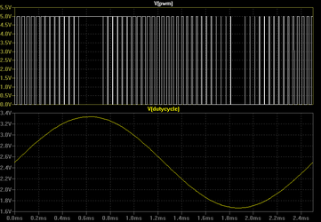
Here the example result from above circuit, to simulate different pwm dutycycle stages, all you need is to alter or manipulate the "DutyCycle" voltage source at 1.66666 Volt for 0% and up to 3.33333 volt for 100% duty cycle. At 2.5 volt, it will be at 50% dutycycle.

This particular example, the "DutyCycle" is a sine wave swinging from 1.666 to 3.3333 volt peak to peak and the modulated pwm signal.
Varying Duty Cycle.PNG

Hope this helps.
 
Last edited:
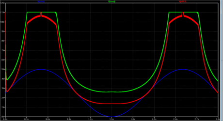
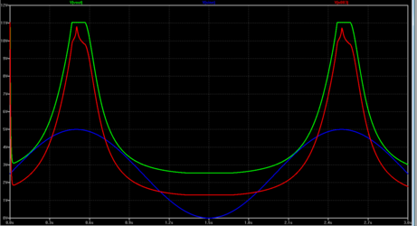
I will definitely try that Bing, thanks. So here's what we have now, Thanks to kayson. And yes I am aware that fets are transistors.

ADC.png

ADCoutput.png

I'm pretty happy with the way the output looks so far. I'm going to use Bing's file so I can check it at different settings to see how it does.
 
I was feeling sarcastic :p Sorry. But it looks good! You've got the full range over what looks like the same curve. If the next sim looks good I think you should buy the parts and build it to see how it responds to the real thing!
 
Even LT1083 is considered low drop out, but its kinda obsolete architecture since its using bipolar transistor as the pass element if the current is reaching above 1 Amp.

If we're expecting at 11.9 volt something at max vout say at 3 amp current, within scope of linear regulator, I think we must look for 1083's alternative like other ldo controller with external mosfet as the pass element.
 
What would you recommend to use?
I'm not sure I see your point, that's like telling a hobbyist not to build a transistor radio because there's something better. I appreciate the input but I don't need the newest electronics bits, I just need it to work.
But no, I'm not expecting 11.9v, I was expecting 11 and I'm good with that. And according to the specs this piece should be able to do 7a, but I was only using the 1083 (mainly because as I am using LTspice it's already loaded) to model with. As I said there are plenty of other options for ldo's, many cheaper as well.
I would be very interested in seeing your solution, the more the better.

Oh and I tried to use your pwm generator and could do nothing with it. The signal was rather bouncy and noisy. I changed my sine wave to a steady output and I can use 0v to 5v to set duty cycle and I have a nice clean signal. Again, simple is usually better, K.I.S.S..

A "better" LDO will have a lower dropout voltage, which is the minimum voltage from input to output. So the LDO you have is probably 1V dropout hence it getting stuck at 11V. If you want a higher voltage, you can get an LDO with better dropout. The way I see it, the point of a fan controller is to lower the speed and noise, so you'll end up running at low voltages more often than high. It won't make a huge difference. That being said, you could probably just pick another regulator and drop it in (maybe switching that feedback resistor too) so it wouldn't be too difficult.
 
Penguin, if you're happy with 11 volt max out, then its the best for you, agree on keeping it as simple as possible. Also that 1083 is one heck of powerful regulator too, with 7.5 Amp guaranteed also built-in thermal and short circuit protection make it quite respectable imo.

Also I've been using it for quite sometime since 90s, shot of my 1083 in TO-3 case (this type of case is discontinued now), trust me, this thing from electronic point of view, its built like a tank and went thru and survived many harsh conditions. :D

attachment.php


If I'm going to build it, not sure at this moment, maybe I will build it with common, easy to find and cheap discrete components, and imagine it will be driving a bulky TO-220 type mosfet for the power section rather than using commercial ready to use ldo controller, no fancy features like short circuit or thermal protection though, but I think I can live with that.
 
Last edited:
I've been meaning to post but my father-in-law is in pretty bad shape.
While I was checking the setup at a steady input I noticed that the majority of the adjustment is in the last say .75 volts. I didn't really thin k about that when I looked at the chart with the modulating signal. I might try changing resistor values and limiting the range adjustment and make some other adjustments to make it a bit better.
For me this problem really isn't a problem as I am going to be using micro controller and can adjust the program.
For someone that would plan on using something like the mobo signal it might not work out that well. But then again it might. Most of the adjustment would be in say the last 25%.
 
Yeah that's what I meant by it not being very linear control. There are a number of things you could do, like adjusting that resistor. But I doubt you'll get purely linear control with that circuit. It still should be good enough though.
 
Back