• Welcome to Overclockers Forums! Join us to reply in threads, receive reduced ads, and to customize your site experience!

4 pin fan PWM signal to 3 pin fan

Overclockers is supported by our readers. When you click a link to make a purchase, we may earn a commission. Learn More.
Would this work? If the fan were placed at Vout.
 

Attachments

  • ADC.png
    ADC.png
    34.9 KB · Views: 528
  • ADCoutput.png
    ADCoutput.png
    20.7 KB · Views: 510
  • PWM.png
    PWM.png
    29.7 KB · Views: 515
It has potential, but I think you need to put the RC filter between the PWM source and the transistor base, not on the 12V supply that you have it on now. That should help make Vout a little less ripply.

Edit: One other thing is that you need to make sure your filter works for a ~25kHz signal, I'm not 100% sure that's how fast the PWM is switching at the moment.
 
That circuit is also going to be impacted heavily by the draw of the fan, which will require tuning the filter for every different fan load. The reason for putting the filter before the FET is really the goal of the FET in the first place - using it as a fixed load for the filter and a buffer for wide ranges of power draw by the fan.
 
25KHz is the standard frequency, some fans (certain nidec models) demand other frequencies.
 
? Ok, it's probably just me being a noob but I don't understand why you would want to filter the 5v signal before the fet instead of filtering the 12v that would be controlled by the fet and driving the fan. If the filter is on the base it's just gonna turn the fet on and off, but a lot slower now. And I'm not quite sure why you would be worried about freq a pwm fan would need as we,re not trying to control it with pwm.
 

Attachments

  • new.png
    new.png
    27.9 KB · Views: 506
And I'm not quite sure why you would be worried about freq a pwm fan would need as we,re not trying to control it with pwm.

Actually, that is exactly what I am trying to do. I want to take a 0-5 PWM voltage, such as the one that comes off the mobo or the one created by Bing's PWM controller, and turn it into a DC voltage between 0 and 12 based on the duty cycle of the PWM.
 
I want to take a 0-5 PWM voltage, such as the one that comes off the mobo or the one created by Bing's PWM controller, and turn it into a DC voltage between 0 and 12 based on the duty cycle of the PWM.

Right, I understand that. But would it not be easier to drive the fet with the 5v pwm signal that would control the 12v. Then use the low pass on the 12v pwm signal instead to get the analog output.

:shrug:
 
Taking a second look, it does look like it's worth looking into. So what I wonder is what happens if you slow the sine wave (it looks like that is what controls the duty cycle) to about 1 Hz, and set the PWM frequency to 25kHz.

Why I ask is that the output of Vout in your first picture looks very non linear, and I wonder if that is just due to the fast switching of the duty cycle. That make sense?

TK
 
Both plans have difficulties:

Filtering the 5v PWM and driving the mosfet in it's linear zone means the fet is burning power to control fan speed, it's going to need a chunky heatsink if it's regulating a 3a to 4a fan (3 amp fan, say a 5v drop to run it at 8v, that's 15w of heat to get rid of).

Filtering the 12v output from the mosfet is going to require some downright chunky capacitors to keep the voltage the fan sees from having significant ripple, this is after all a 3-4 amp fan!


Now if y'all're thinking more along the lines of a 0.5 amp fan, both plans are a lot easier to use.

Personally, I'm looking to control a four amp Delta screamer, I'll probably end up building a buck controller around an ATtiny85 MCU.


EDIT:
Where is this sine wave coming from, anyway? Duty cycle isn't going to change especially quickly, not on the timescale of a 25kHz PWM signal at least.
It's important to remember that as far as the controller is concerned it's a fairly fixed duty cycle, the fastest I would expect it ever to move is around 20% per second, that's if you go from idle with full power saving features to full overclocked load on a fairly small cooler.
It certainly won't be cycling from 0% to 100% and back in 26ms.
 
For a 4a fan, call it a 3 ohm resistor. It's not especially accurate, the fans don't draw a steady load, but it ought to work.
Be sure to test the circuit with 6 ohm (2a), and 12 ohm (1a), and 24ohm (.5a) resistor loads too. If it can keep all four of those happy you've got a winner.
 
You can put a 3 ohm resistor between vout and ground to simulate a 3 amp fan, and increase it up to 24 ohms to simulate a 0.5 amp fan

Edit: Oops, Bob beat me to it.
 
T=K, I'm also watching this thread closely, too bad I can't contribute too much cause now practically I have no time to sit down quitely and sketch the circuit for this purpose, and also I think this ain't simple circuit too. :-/

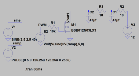
Imo, the pwm signal which is switching at 5 volt, it needs to be converted to pure DC with low pass filter first to have a clean signal free from those pwm frequency, and then this converted "clean & stable" voltage level will be acting as reference for the final fan output voltage.

Although this sounds simple, it needs further processing for the offset and gain before handling it to later power section, which could be plain-jane linear power regulator or more advance and complicated power switching controller.

I believe, this offset and gain level are like manual one time adjustment, probably to be implemented like sort of a pot or trimpot. This is crucial since we can not do direct translation like 0% to 100% duty cycle at the pwm signal to 0 - 12 volt.

Why ? Few scenarios I could think of ...

For example people want to hook this converter at the mobo's pwm header instead of pwm controller :

Example scenario :

Probably because of the bios/mobo built-in program limitation, the mobo pwm header can only producing somewhere like 25% when the cpu was idling and upto 85% duty cycle at fully loaded cpu, instead of pure 0-100%, this can creates complications such as :

The user wants that when at lowest 25% duty cyle, this converter will outputting lowest possible volt for the fan but still spinning, and while at 85%, this will translate to max 12 volt for max fan speed.

..or ..

At the same 25% duty cycle aka idling cpu, he wants the fan to be fully stopped to reduce the fan noise to zero, this alone is like setting the output to 0 volt, while at 85% dutycycle, its expected to drive the fan around 10 volt since the owner 'feels' it is the max tolerated speed. :-/

Remember, when driving fan with voltage, different fans behave differently at low voltage, some will rotate at minimal speed at 5 volt, but some will not rotate at all if the voltage is under 7 volt and etc.


Other example scenario :

The owner is using pwm controller capable of delivering 0-100% signal, and with only single pot from this controller, he is able to control his mixed pwm fan and number of classic fans through this converters, and he is expecting ..

At 0%, it will be driving the fan at 5 volt, cause he doesn't want his fans to stop rotating at all, and while at 100% will be equal to 12 volt for max speed. Probably this is for his rad's fans.

And he has other identical converter and wants it to behave like this below for his case's fans ...

At 0%, this will be at 7 volt since that is the lowest voltage for case fans to spin up, and while at 100%, he wants that the output only maxed out at 10 volt since this is the max speed that his ears are allowed to tolerate. :D

Hope you see why direct translation from 0-100% to 0-12 volt is not a good idea, cause I'm worry it may not interest many people to participate in building it cause lack of flexibilities like I mentioned above.

Just my 2 cents.
 
Last edited:
^ A lot of good points. What if I want to use this to power a water pump that only switches on at 6v?

Seems like whomever ends up building this will need a DMM and some time to fine-tune it.
 
After I did some looking around I came up with this. Although the lt1083 is kinda pricey, at about $8 a pop, they're are plenty of others from other manufactures for much cheaper. Many of them from 1.5A and up, the lt1083 goes up to 7.5A. The output shows at just under 4v to 11v. Let me know what ya think.

ADC.png

ADCoutput.png

The blue line would be the pwm duty cycle, but up is 0% and down is 100%. The green would be to the fan and red is from the adjust.
 
It'd need some form of inverter, mobo control would get rather confused by the backwards PWM response :D
 
That's a really clever way of doing things. (Also nice trick to sim the multiple duty cycles). I'm a little confused, though. If your B1 source has an output of 5V if sine > pulse, wouldn't sine at 5V mean the B1 source is always at 5V? So 100%? Also, the higher your adjust voltage is, the higher the output. So at 100% duty cycle, your mostfet is hard on, bringing point2 to ground, and giving you your lowest output...

Can you do a few sims of constant duty cycle? I'm curious to see how much ripple there is at the output. Maybe 25%, 50%, 75%, and 100%? You should be able to do that just with the PULSE parameters.

One important thing: I'm pretty sure the PWM output from a mobo is open drain. Meaning you'll need a pull-up resistor to 5V on that MOSFET gate. When you actually make it.

Edit: You could also get more linear control if you have the pwm signal push constant current into a capacitor. This gets you a perfect ramp voltage on the cap. The longer the duty cycle, the higher the voltage at the end, and the higher the voltage on the adjust = higher output. You could also make your own LDO with an op-amp and a mosfet to save some money.
 
Last edited:
well, I went back and looked at it and unfortunately it is inverted. I'll mess with it later to see if I can flip it around. Guess I got myself backwards while I was up last night.
 
Back