• Welcome to Overclockers Forums! Join us to reply in threads, receive reduced ads, and to customize your site experience!

5700 XT Junction Temperature

Overclockers is supported by our readers. When you click a link to make a purchase, we may earn a commission. Learn More.

CrackaPlz

New Member
Joined
Sep 24, 2019
My System:
CPU: Ryzen 7-3700X
GPU: 5700 XT (XFX Model No. RX-57XT8MFD6)
Motherboard: Asrock x570 Steel Legend
RAM: Corsair Vengeance Pro RGB – 16 Gb
Case: Cooler Master HAF Stacker 935
CPU Waterblock: EK Supremacy
GPU Waterblock: EK Vector Nickel-Plexi, 5700 XT with associated backplate
Radiators: 2 – XSPC EX240 2 X 120

I recently completed a long time project of mine to create a hardline custom water cooling with even a custom reservoir. It was my first time ever water cooling so I knew it was a lot to bite off but after tons of research and planning I finally built it. I’m still finishing up cosmetic items but it’s been running for the last few weeks (relatively) reliably. The CPU and GPU are in parallel loops right after their own radiator. My idle temperatures are about 40 C for the CPU and GPU. Under load such as gaming I will get up to about 50C-CPU and 58C-GPU. That seems fine to me but my biggest concern is the GPU junction temperature. Under load like with Firestrike it immediately spikes to 90, in about 10 minutes in it gets to 100C. Originally I was seeing 110C even faster than that. I think the high temps may have crashed the card a few times while playing Borderlands 3 but that game has its own bugs so I'm not completely sure.

Since noticing this, I have been working with EK but their response is about one time a day so I am looking for some more timely help here. I have removed the block, cleaned and reapplied the thermal paste, pea method on the second try as opposed to the X that EK’s manual calls for. Thermal pads seemed to be sitting nicely as well. What I think is causing my issue is that the water block doesn’t fit flush with the card, causing it to curve when I torque all the screws down. One standoff on the I/O port side would not sit correctly and I practically had to strip the screw to bring it in. I didn’t want to do it but EK said it needed to be flush. I have confirmed through XFX that this is definitely an AMD reference card and they made no modifications to the board.

Is there anyone else out there water cooling a 5700 XT? Have they dealt with similar junction temperatures that they can’t bring down? Any other suggestions on how to fix this? I know both Alphacool and Corsair have similar blocks for the 5700 XT but I would love to avoid that headache if I can.
 
I would advise a thin spread of paste or a generous X. The GPU is a direct die, in other words there is nothing to distribute or even out any hot spots. I would be concerned about the pea method leaving blank spots or bubbles. Also don't be afraid to use a little excess paste as long as it's not a conductive or capacitive variety. I would err on the side of being generous.

It does absolutely need to be flush, at least in terms of the cold plate and the GPU surfaces mating. It shouldn't require high amounts of torque. For installing my GPU block, I ensured the screws were snug, but no more. In fact too much torque could cause the block or card to curve as well. Can you please take pictures of the standoff / problem area? You may be better off omitting a screw there, if it's not part of the main cooler mounting screws. There could also be a manufacturing defect in the block and/or card. Is this relating to the IO shield? Some EK blocks come with a single slot IO shield. The card or block should absolutely not be curved or bent when the block is installed.

I don't personally have experience with the 5700 XT, but I do have a water cooled vega 64. One thing that is important to note is that AMD cards report a hotspot or junction temp which is the hottest temp on the card. There is no equivalent temperature reported by nVidia cards, so comparing temps between the two brands is futile. There have been a lot of reports of high junction temps, including temps reaching the tjmax or throttling temp of 105C, however this appears usually with blower coolers and poor case airflow. It is definitely a sign of a problem in a custom loop.
 
Thank you Zerileous. I appreciate you taking the time to write out your response.

The first time around when applying the block, I went with the X method based on EK's manual. It was definitely on the generous side for the amount of paste but still, my hotspot temperature was hitting 110 C consistently when under load. I thought maybe I did something wrong so that is when I started the conversation with EK. They recommended the pea method at that time because it can be more consistent to accomplish.

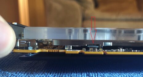
The standoff problem area is not the I/O shield, it is on the block toward the I/O shield. I've attached an image where you can actually see gaps between the standoff and the card as well as a gap between the backplate and card. This picture is before EK told me to tighten that all the way down (but as I said, it basically requires stripping the screw to accomplish).

Problematic Standoff.jpg

Honestly, right now I am leaning toward a manufacturer's defect but I'm not sure who to blame.
 
How did the thermal paste look when you removed it the first time? Was it even? At the end of the day all that matters is an even applications, most methods get you there most of the time, it's just the impact of not having that is more significant with a GPU.

From your picture it doesn't look like anything contacting the plexi surface to cause that, maybe the block or card is not straight. I believe my block came with a number of plastic washers to be used in certain places during the mounting, but I don't remember exactly where. That said it looks as though a washer would fit there. Are you certain that all of the little washers are installed correctly and in the correct locations? I would look very carefully at the block to make sure nothing is contacting it to create the gap as well as attempt to ascertain if any of the 3 parts is bent (PCB, block or back plate). The block actually appears curved in that picture, but photographs are not really accurate in determining such things, as lens design, angle of the photo, etc impact the perception of straight lines.
 
The first time around it definitely looked like I had too much thermal paste but the coating was at least even. I actually pulled the block off again last night with the pea method and I managed to have solid coverage along the whole GPU die.

EK suggested the screws as well even though I used the screws and plastic washers provided with the block. I took a bunch more pictures during disassembly and sent them along to EK for their consideration as well. For example, you can see that the thermal pad isn't even in contact with the metal of the block.
Thermal Pad.jpg

All the pieces are separated again right now but I won't reassemble them until I get more input from them.
 
It appears just that one choke, perhaps... but I can see metal from the blcok inside in what I assume makes contact? You can tell by the thermal pad. Are chookes even supposed to be cooled by that block? What do the instructions say?
 
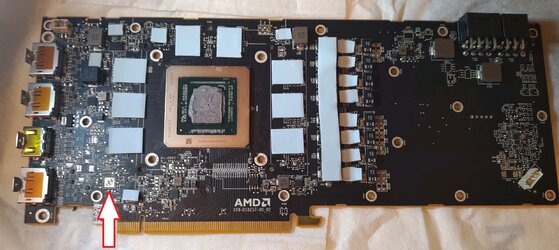
I pulled up the manual again and it does appear that I have that thermal pad wrong. So that's a good catch. Thank you! It looks like I have the rest of the components covered correctly except that pad needs shifted over to the component I marked. Do you by any chance know what component that is? If I was more knowledgeable about the individual components I might have caught this in the beginning.

GPU Board.jpg

Page 6 of the this manual for thermal pad reference (https://www.ekwb.com/shop/EK-IM/EK-IM-3831109819371.pdf)
 
It doesn't look like it goes there either. I don't see a chip in on that pad...

It looks like the right spot according to the manual. You're saying there doesn't appear to be a chip there to cool though? I wonder what's up with that.

When installing the block I would make sure you first do the four screws closest to the GPU, and tighten them in a cross pattern (like lug nuts). If the screws are labeled in this fashion:

1____2
|____|
3____4

Then you would tighten each screw by approximately half a turn in the following order: 1, 4, 2, 3, 1, 4, 2, 3, 1...and so on until they are all snug, then work outwards. Can you look at the thermal pads and see if they are indented from making contact (except of course misplaced one noted above). Also verify that the correct thickness thermal pad was used in each location. For example, if a 1mm thermal pad was applied to the GDDR nearest the IO shield, it would prevent the standoff from making proper contact. I'm guessing EK already went over most of this with you, but I just wanted to ensure it was all checked.

For your thermal paste, I see a corner that doesn't appear to have paste on it. Not sure if that was rubbed off in removing the block or not there in the first place. For a GPU even an tiny exposed corner can cause huge problems.
 
It looks like the right spot according to the manual. You're saying there doesn't appear to be a chip there to cool though? I wonder what's up with that.

I can't exactly explain what that potential component is supposed to be unless someone knows where to find a diagram for an AMD reference board. XFX confirmed that bit for me.

I did use a cross-pattern focusing on the GPU screws first. Then followed up with all the remaining screws but again I tightened them slowly with half turns all the way around.

For your thermal paste, I see a corner that doesn't appear to have paste on it. Not sure if that was rubbed off in removing the block or not there in the first place. For a GPU even an tiny exposed corner can cause huge problems.

This is rubbed off on accident when I was separating the block and moving things around on my table. I took a look at the thermal paste on the water block side and you can see full coverage there. I can upload a photo of that side as well if you want.
 
I believe you, I just wanted to double check. Whatever is going on it does appear to be the same on this board
. Unsure why they would have a thermal pad placed there, good question for EK I guess. The stock reference cooler (from the video linked above) does not appear to contact that part of the PCB. However it does have a pad for something near the lowest GDDR6 module on that side of the GPU.
 
So think I finally managed to get this running with good temperatures, maybe 60 C, under load. I want to thank everyone who has been chiming in here, offering advice, and suggesting where to look next. Thank you for offering some of your time Zerileous and EarthDog.

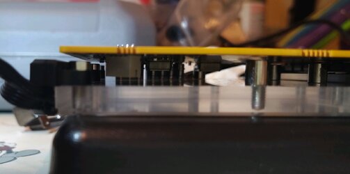
Last night I went through assembling and disassembling the block a couple times to verify alignment issues and how to keep them under control before adding some new thermal paste. I did have the one thermal pad in the incorrect location but neither spot comes in direct contact with the block so I don’t think it was driving my problems. As Zerileous said, you definitely start with the GPU, crossing back and forth. Take a look at the picture below and you can see that with just these four screws, you actually get the board to bow outward from the block.
Curve.jpg

I also found out that several screws with longer thread lengths made their way into my bag. I measured the threads with my calipers and for this block you don’t want anything longer than 4 mm for the main connections. I am thinking that I had some binding going on due to a combination of a few bad (long) screws along with the curvature in the board. This was probably enough separation for the spike in hotspot/junction temperatures that I was seeing.

Thank you again for the help in figuring this out. Later tonight I’m going to run several more stress test just to make sure everything is good to go.

For future reference, issues I identified:
Several screws longer than the 4mm thread length recommended
Curved board, causing some type of binding
Misplaced thermal pad (probably not critical)
 
ahh for sure if one of them was bottoming out before placing adequate tension that would be a big cause. Is 60C your junction temp now? That's excellent! Thanks for letting us know how it turned out.

I think that thermal pad has to be a misprint by EK. If you look at the reference tear down there is something with a thermal pad on it near that area, just towards the IO shield from the bottom GDDR6 module. I doubt it's critical though.
 
Yeah, 60C is the junction temperature under load for me now. Big improvement! I even unlocked the power limit with MSI afterburner and it was only getting to about 85C for junction temp. Again, thank you for all the help!
 
Back