• Welcome to Overclockers Forums! Join us to reply in threads, receive reduced ads, and to customize your site experience!

AX500-A Blue Storm POTS Exposed

Overclockers is supported by our readers. When you click a link to make a purchase, we may earn a commission. Learn More.

Slake

Senior Member
Joined
Jan 12, 2001
Location
Knoxville,Tn
As Oklahoma Wolf pointed out a few months ago, Silent PC review did a great review of the AX500-a HERE . This is a great link for overall performance/ specs and glamour shots. So I am sure that after you read it you will just have to have one. I bought mine back in October based on the great reputation of Fortron products by the likes of The WOLF and Larva. Anyway they gave me a new appreciation of the impotance of a reliable high quality PSU. That and the fact that a PSU included in a $30.00 case killed my last system. Fried my Asus CUSL2-C Black Pearl and my humongous 40 Gig Maxtor- ah, Yeah ! It's been that long since I had a PC to OC.
I came over to the dark side to build the system in my sig. The Blue Storm was the very first component I bought. I didn't get all my parts together until around the middle of January, so I had lots of time to kill, and I took the PSU apart and took some great pics, intending to post a mini review. The OC gods had other ideas and those pics were lost when a bad OC attempt necessitated a re-format. :bang head . I noticed low readings on my 12v rail in Asus Probe and in MBM-5 also before Bios 10007 killed Probe. So I went and got me a Digital multimeter and set about to adjust the pots. Never having done this before I perused the forum and the internet trying to find pics of the pots location and instructions. NOGO - So I kinda used info found in this forum about other PSU's (none were for Dual 12v ATX 2.x Spec units) and just winged it.
This thread is by no means intended to be the definitive how to on modding the Blue Storm's Rails; just a photo guide of my attempt to do so and a place for those more knowledgable *cough-OKWolf-cough* Larva*-cough* to correct my mis-information. Since the AX500-A seems to be a very popular PSU I hope this thread will be of use to others.
So Here is where my project begins:
HavingFunYet.jpg

Now, I bypassed the "How to remove the Cover" Part, 'cause if you cant do that without help, turn back now. We gonna be messin' wif Hi-voltage- lite Yo A** up!! stuff here in a few minutes. Just remember you don't have to remove the screws that hold the lighted switch to remove the cover. Yes I did do that the first time, but ahh... :rolleyes: I didn't have any help....

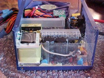
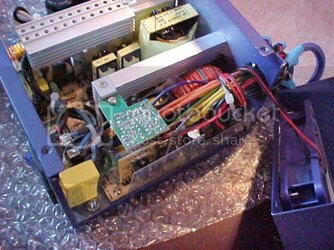
Here is a general overview showing the caps.. v
Overview.jpg
Opposite side v
Overvie2wadj.jpg
 
Last edited:
- BE WARNED!! YOU CAN HURT/KILL YOURSELF and/or FRY YOUR COMPUTER and/or BURN YOUR' HOUSE DOWN IF YOU TRY THIS -
Proceed at your OWN Risk. Myself, These Forums, I-net OR ANYONE other than yourself can be held responsible for any damages caused by your attempt to do what I did.​
I-8 ??​

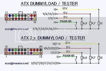
Useful Power connectors Pin info v
20and24pinATXPin-outs.jpg
Image is from Tweakers Net Forums

This is kinda' handy for identifying where to read your voltages. 12v wire is yellow and the 5v wire is red, ground to black - duh
atx12v.gif

IMPORTANT: Before continuing, turn your PC off- pull the power cable loose from the back of the PSU, then press the power on button twice- This will discharge the power stored in the capacitors and make it safe to proceed to making the PSU think the ATX connector is attached to a mobo- THUSLY;
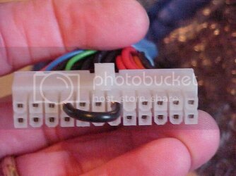
Keep in mind upper row is the row of pins that has the locking "nib" and that the pin numbering starts at bottom left and each pin increases by one number as you go right, then the next sequentially numbered pin after the last pin on the bottom row will be in the upper left corner. See diagrams above.
I used a piece of wire between the power on pin #16 to ground pin #19 because I have a 24pin ATX connector, if you have a 20 pin connector, run the wire from #14 to 17 (or any black wire). If the numbers are too confusing- just connect the pin with the green wire on the top row (the row with the locking nib) to any pin that has a black wire.
Jumper.jpg
 
Last edited:
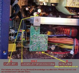
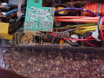
This is my initial understanding of the locations and functions of each of the 4 adjustible POTS I found. I am not at all sure that these are correct , HENCE I labeled them A-B-C-D- so that if anyone cares to enlighten us as to the correct function of each POT they may refer to the letter associated. This will keep us all on the same wavelength and make references to individual POT's clear as to which one is being discussed.
POTSABCD.jpg
locationpotd.jpg
 
Last edited:
OK, when I had all of the above outta the way, I plugged the power cord into the PSU and turned it on. No smoke. Good.

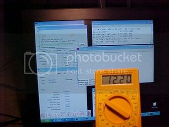
I turned my digital multimeter to the 20v scale and tested the 12v rail by inserting the red probe into the Yellow post of a molex connector and the black probe into a black one. MBM and probe had been reporting 11.65 volts on this rail consistantly since I built the system. Occasionally it would drop down to 11.5x which greatly concerned me. I was pleased to see that the meter reported a steady 12.20volts even under a great load. This pic shows the voltage readout while running Prime95, SuperPi and copying a CD rom to the hard drive. It may have dipped a little to like 12.17 or so, sorry can't remember. Notice the MBM-5 reading is reading .55v lower than the meter ! Crappy on board monitoring. So I was really OK all along on the 12v Rail. I adjusted the 12.v rail up to 12.65 using the multimeter and Pot A -see post #3 above.
Stable12vrailatload.jpg

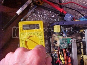
I didn't have anyone to take pics while I waorked, and wasn't real comfortable using the camera myself while adjusting the rails, so action photos are kinda skimpy (read one shot of adjusting the 5v rail)

I used the pinout diagrams from previous post to determine how to read the voltage on the 4pin 12v connector. The red probe goes into the pin closest to the locking "nib" and the black ahh.. yea the one furthest from the nib. The 4pin 12v reading was 12.65 also. So I turned my attention to the 5v line.
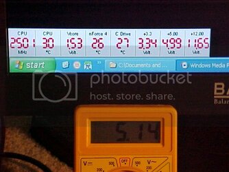
Here is my initial reading of the 5v rail on the meter.
5Vdifference.jpg
You can see that MBM-5 is reporting .15v lower. No biggie- I bumped it up to 5.33v using Pot D - After adjusting Pot D, I went back and measured the 12v rails again and they had changed. This must be due to the power sharing I've heard of (but don't even begin to understand) between the 5v and 12v rails.
Adjust5vpot.jpg
 
Last edited:
Bottom line; don't believe your on-board voltage and temperature sensors. Get a digital multimeter and check those voltages.Use correctly mounted probes if your anal about temps, but you know when your stuffs too hot and I am ok with inacurate temp readings as long as they are consistant and proportional. (read I botched the placement of the thermal probes on my superflower Fanmaster :shrug: ) I could have left my rails alone and been just fine. But I just hate looking at diagnostic and system monitoring software that tells me my hardware/cooling ain't up to snuff. It'll give ya a complex, plus ya gotta explain wacky readings when you upload a benchmarking screenshot that includes a temp reading of 85 deg Celsius but you seem oblivious to it, or how come you aren't worried about your MBM voltage reading 0f 10.87 on the 12v rail.
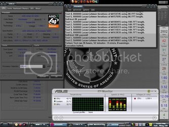
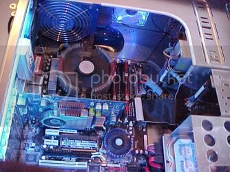
Final result MBM still reads low, but the voltages are adjusted High enough that even MBM shows they are slightly over 12v and 5v and my meter assures me that they are within tolerance on the hi side at 12.65v and 5.33v.(edit: Slightly over Tolerance- Thanks Know Nuthin) My system is purring happily along and this is what I see now when I check my voltages.
Prime26hrsbios1010.jpg

AX500-A Blue Storm at Work
LitUpBottomup.jpg
 
Last edited:
Looking good so far. Keep in mind that the 12v line at the drive molexes is 12v1 on this unit, and adjustments made to it should have no effect on 12v2 being used by the CPU. You'll have to get 12v2 at the 4 pin 12v connector.
 
Thanks Oklahoma Wolf- I lost about 35 minutes worth of writing information peppered with witty observations and remarks before you posted. I did measure the 4pin 12v line and it is now also 12.65. I actually measured it again after reading your post, just to be sure LOL- :p - BTW is that too high? //12.65 and 5.33 //Or can I leave it there and be safe? I got totally confused while turning those pots. Voltages got all wacky and I just left it alone for awhile and tried again. I am not really comfortable with the labels I put on the pots in post 3. I am hoping someone will correct me if they are wrong. Thanks for the feedback man. Your hard work in providing us with great PSU info and advice is appreciated.
 
Last edited:
I believe fortron rates these for 5% deviation (11.4-12.6, 4.75-5.25v) , so 12.65 is just slightly over that but 4.33 is way under. if you mean 5.33, that's just slightly over as well.
 
Know Nuttin said:
I believe fortron rates these for 5% deviation (11.4-12.6, 4.75-5.25v) , so 12.65 is just slightly over that but 4.33 is way under. if you mean 5.33, that's just slightly over as well.
Thanks man. Yea, I did mean 5.33.(I'll edit that) At 3AM I guess typing errors are to be expected eh?- lol- Well, maybe I will adjust 'em down a little. Pain in the keister tho to take out my PSU with the wiring behind the mobo tray. Prolly not tho :p
 
slightly off topic but that is one beautiful interior case shot; what is that thing on the northbridge and how much did it cost? :p
 
zer0nix said:
slightly off topic but that is one beautiful interior case shot; what is that thing on the northbridge and how much did it cost? :p


he doesn't have a northbridge. and anyway, thats the cooler that came with his boards southbridge. His northbridge is integrated onto the processor (like all Athlon64s)
 
zer0nix said:
slightly off topic but that is one beautiful interior case shot; what is that thing on the northbridge and how much did it cost? :p

Thanks for the compliment zer0nix, I plan on posting some more pics of my mildly modded case in the appropreate Forum soon. that is actually a Thermaltake Blue Orb I bought a long time ago intending to upgrade cooling for an old geforce2 that had passive cooling. Never got around to installing it. I took off the P.O.S. Asus fan and replaced it with the Blue Orb before I ever fired the system up. Those puny Asus fans are famous for failing quickly and if they do last are very loud. When I eventually get my 2nd 6600GT and go SLI, I'll have to modify or replace the Orb. Does a great job though.

And SolidxSnake I believe you are correct in referring to the nForce 4 single chip solution as the Southbridge due to the memory controller relocation to the CPU as you mentioned. Seems like most posts I've seen though do refer to it as the Northbridge.
 
^bump^ -Because there are a lot of questions about this PSU lately. There is a link to a great review of the AX500-A in Post#1.
 
SolidxSnake said:
he doesn't have a northbridge. and anyway, thats the cooler that came with his boards southbridge. His northbridge is integrated onto the processor (like all Athlon64s)

shoot i always thought the chipset was the NB no matter what, lol thanks for that info Snake! man i cant believe i didnt know that.
 
heh

the chipset is the NB and SB. but most people just think of the NB cause its more important (the SB is for I/O from HDD and the likes, NB is memory controller, between processor and RAM and expansion ports, I believe)

btw... does the BlueStorm have a 3.3pot?
 
SolidxSnake said:
heh

the chipset is the NB and SB. but most people just think of the NB cause its more important (the SB is for I/O from HDD and the likes, NB is memory controller, between processor and RAM and expansion ports, I believe)

btw... does the BlueStorm have a 3.3pot?

Good question, and part of the reason for this thread. I am hoping someone with more knowledge than I can answer that,and also confirm or correct the Potentiometer identifications from post #3. I may take the PSU apart again and experiment a little when I get time. Busy all week so it will be a while. I did adjust pots b&c a little but I don't believe they caused any movement on the multimeter. I think I correctly labeled them as overvoltage adjustment pots. That is supported by another post in this forum also.
 
Last edited:
I'm beginning to wonder if maybe Pot A is the 3.3v pot? I was nervious/tired when I adjusted them. Wish it wasn't such a pain to remove the PSU. I have the wires routed behind the mobo tray.
 
Back