• Welcome to Overclockers Forums! Join us to reply in threads, receive reduced ads, and to customize your site experience!

[Build Log] Project Azure (700D)

Overclockers is supported by our readers. When you click a link to make a purchase, we may earn a commission. Learn More.

Draizien

Member
Joined
May 11, 2010
Project Logo OCF Small.jpg

Concept
This build is based around the familiar 700D, however with some significant modifications beyond the norm. Perhaps the most significant of these is the addition of a triple 120mm radiator in the front of the case. Secondly, the standard quad 120 mm radiator will be placed up top, however the rad grill will be placed in-lay with the top and the seams epoxied, with the end product looking as if the grill was built into the top. Additionally the entire interior of the case is being rebuilt, fabricating a new motherboard tray and midplate along with a side wall which will completely section the interior into distinct regions.

Theme
The design of this build is going to be based on building upon the straight, sharp lines and the sleek, clean look the 700D already possesses. The color scheme will be white and as the name of the project suggests, accented with various shades of blue.

Hardware
This build started quite sometime ago and consequently the hardware was also purchased during this time, so the hardware is somewhat dated now, however a fair amount of the modifications are made around these parts so it will have to do. With that being said, here is a list of the majority of the items being used.

Hardware
  • CPU: i7 930
  • Motherboard: Gigabyte X58A-UD7
  • GPU: EVGA GTX 580
  • Memory: 6GB G.Skill Ripjaws
  • Storage: Mushkin Callisto 64 GB, 2x 500 GB Samsung Spinpoint in RAID 1
  • Controller: Aquaero 5 Pro

Radiators & Water Blocks
  • Radiators: Swiftech MCR 120.3 & 120.4
  • CPU Block: Aquaero Kryos, nickel top
  • GPU Block: EK 580 FC, nickel & clear plexi
  • NB Block: Mips UD7 Fusion block, nickel top
  • Pumps: 2x MCP 350
  • Reservoir: Phobya Balancer 150 ml, nickel

I will have the bottoms of the CPU & NB block nickel plated, and due to damage the nickel plating on the GPU block has suffered, the old plating will be stripped and redone.

Additionally, the fans being used are GT14's which have been modified to allow for the unorthodox mounting the fans will require as well as being painted white.

Due to having multiple 45 and 90 degree fittings (~12) I decided to go with two pumps to help with the added restriction. I already had two pumps and adding an extra really did not present any modding complications so there was really no compelling reason to stick with just one particularly since I have had a pump die in the middle of the night resulting in a nonfunctional PC for a couple days :( so the redundancy of pumps will be welcomed. One of the pumps being used was originally a MCP 355 and in-fact was the pump which died due to the circuit board being burned. The repaired pump will end up essentially being a MCP 350, which don't seem to have the overheating problems the 355 has so hopefully it does not happen again.

With that, let us begin and get to work!

 
Last edited:
Front 120.3 Radiator: Part I

When initially planning this build, I wanted to do something with this case, which to my knowledge has not been done. So following some careful thinking, measuring and consideration of the functionality I required in a case I decided a 120.3 radiator in the front was, with some effort, a doable modification. The one question now was how to carry out such a task. Up first was cutting the holes for the fans. Now since a 120.3 rad is going take up front bay slots, the holes could not be directly cut into the front plate unfortunately. So the next option was a rad grill. Due to needing a grill with an unconventional width, a custom grill was going to be necessary.

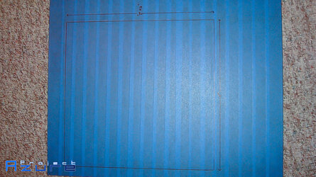
The cutout traces were made.

120.3 Grill Cut Markers.jpg

The cuts made and rough edges filed.

120.3 Grill.jpg

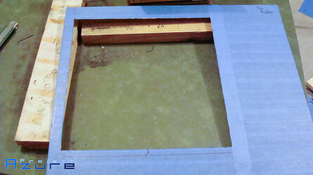
Now it was time to set out on the task of cutting through that thick aluminum front plate of the 700D. Sad to say a dremel was just not cutting it so to speak therefore it was necessary to break out the jigsaw and try to get a rough cut, hopefully minimizing the amount of filing required.

So the cutout marks were made.

Front Panel Cut Markers.jpg

The rough cut, and I truely mean rough :eh?:, was made.
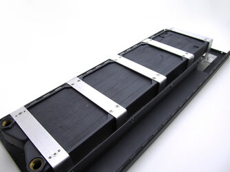
Front Panel Rough Cut.jpg

Next up was a healthy amount of filing, giving quite the workout along with a metal shard to the eye.

Front Panel 1.jpg

Front Panel 2.jpg

Front Panel 3.jpg

The only remaining task was to fabricate the mounting brackets. However, before this was completed, a bit of inspiration struck and after looking at what the final product was going to look like I knew I could do better. At that point I decided nothing short of a completely redesigned front panel would do. Which we will pick up at a later date in part II, however I will give a quick teaser.

Front Plate Teaser.jpg

To be continued...
 
You know this is gonna be a good project when you've photoshopped a great looking logo for the project!

...and the fact that, that brushed steel picture looks fantastic!
Definitely keeping up with this one :D
 
Side Panel Modifications

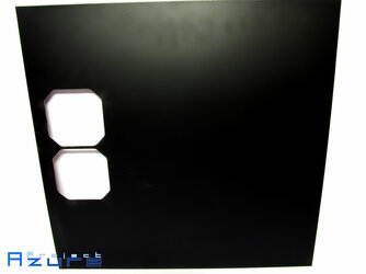
As most of you are aware, the 700D comes with no window in the side panel which played a role in choosing the 700D over the 800D as the window goes down to far and the gentle curve of the 800D window does not fit the theme of the build.

Window cutout.

Side Panel Window Cut Markers.jpg

Rough cut.

Side Panel Window Rough Cut.jpg

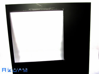
Filed down.

Side Panel Window.jpg

The window is not yet finished, but it will be an inlay window in that the window will be flush with the side panel and it will be mounted to the window with standard mounting tape as opposed to screws.

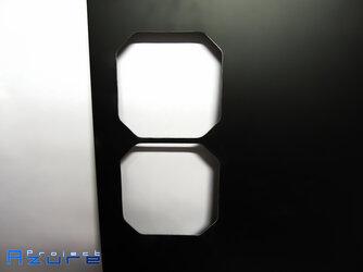
Because of the way the interior of the case is going to be sectioned off and the added 120.3 rad to the front it was necessary to have a way to remove the excess air from the front compartment. The solution was to cut fan holes into the other side panel.

Rough cut.

Side Panel Fan Holes Rough Cut.jpg

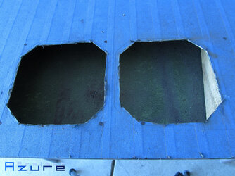
Time for the filing.

Side Panel Fan Holes 1.jpg

Side Panel Fan Holes 2.jpg

That brings this update to an end.
 
Top 120.4 Radiator

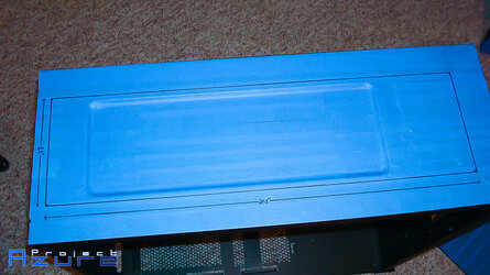
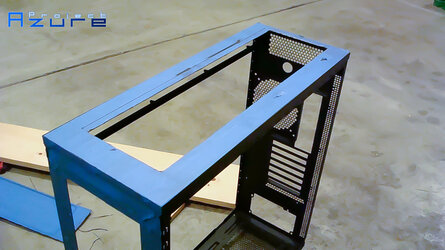
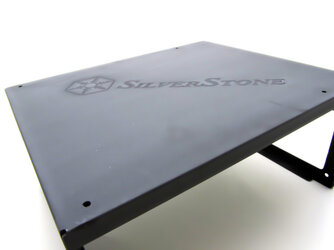
To keep consistent to the theme of the build, I wanted the fan holes to be a part of the top itself. There were two potential ways to achieve this, either fabricate a new top from scratch which certainly would be the most time consuming or keep the original top and figure out some way to take a 120.4 radiator bracket and mount it to create the appearance of a single piece. Ultimately, I went with the second option.

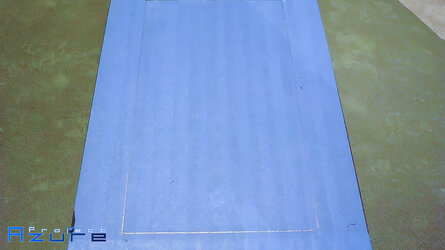
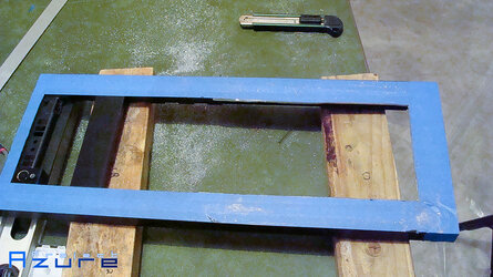
The area to be cut was marked off and the rough cuts were made.
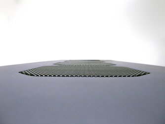
Top Cut Markers.jpg

Top Rough Cut 1.jpg

Top Rough Cut 2.jpg

This was followed by filing to get a clean cut.

Top Cut.jpg

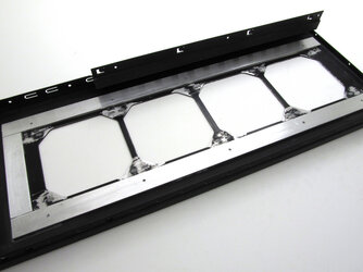
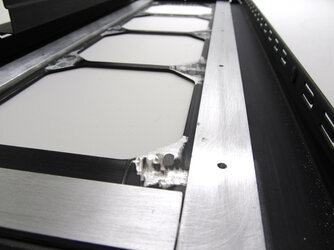
Now due to the thickness of the radiator grill it was necessary to create a mounting bracket that would allow the radiator grill to sit flush with the top. This was done by using metal bars with different widths to create an overhang with sufficient depth which the radiator grill would be mounted to.

Mounting Bracket 1.jpg

Mounting Bracket 2.jpg

Mounting Bracket 3.jpg

The next task was to attach the mounting bracket to the top itself. This was achieved simply enough with high strength glue. Minor spoilers of future updates in the pictures below showing the mounting brackets in place.
Mounting Bracket 4.jpg

Mounting Bracket 5.jpg

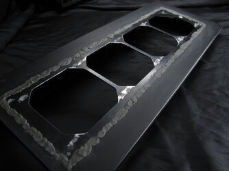
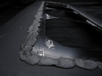
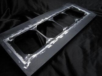
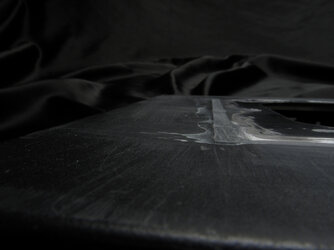
The radiator grill itself was then put in and to fill the gaps I used metal epoxy which I could then sand down to create the flush look. The idea then is after painting it will look like one complete piece.

Top Panel 1.jpg

Top Panel 2.jpg

Top Panel 4.jpg

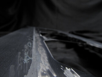
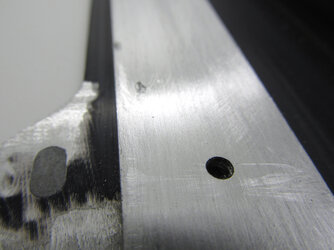
This was then followed by a healthy dose of sanding down metal epoxy which is none to pleasant. In hindsight I should have gone slower with the sanding as I used the dremel to quickly sand down a lot of the metal epoxy but this put some rather deep scratches into the metal itself greatly increasing my work in the future.

Top Panel 5.jpg

Top Panel 6.jpg

Top Panel 7.jpg

Since I wanted a completely flush look and also epoxied up the screw holes in the radiator grill it was necessary to create a new way to mount the radiator. This was done by creating brackets which would mount on the underside of the radiator and screw into the metal bars which the radiator grill was mounted to.

The holes were drilled into the top mounting bracket.

Top Panel 8.jpg

Top Panel 9.jpg

Top Panel 10.jpg

The end product then looks like

Top Panel 16.jpg

(Some of those screws are temporary)

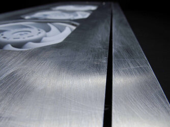
The last step then is the task of painting the piece with primer and sanding down to create the flush look. As mentioned previously the method in which I sanded down the epoxy created a lot of deep scratches which meant that an excess of primer along with hours and hours of wet sanding before all the scratches were filled. I was quite concerned at first as it was not looking as if the scratches were going to go away, however in the end with a fair amount of determination the scratches eventually were filled and the end product gave a piece that looks like one whole piece. There are still some scratches in the pictures, but this is due to carelessness on my part with tools :eh?:.

Top Panel 11.jpg

Top Panel 12.jpg

Top Panel 13.jpg

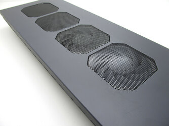
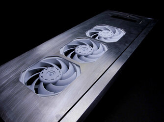
Finally, here is a rough idea of what it looks like with the radiator, fans and grills all installed.

Top Panel 14.jpg

Top Panel 15.jpg
 
wow this is looking fantastic! Great work done on the top piece, very inspirational!
 
Front 120.3 Radiator: Part II

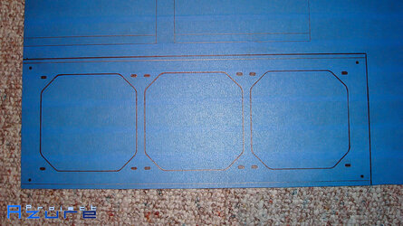
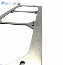
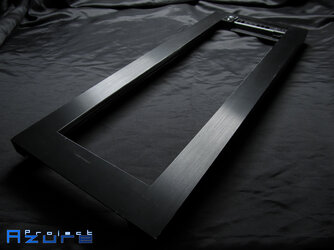
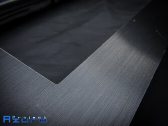
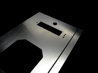
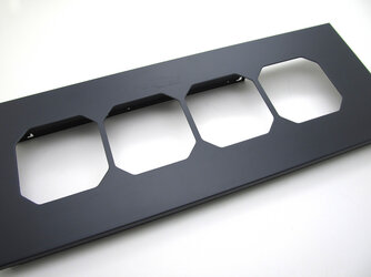
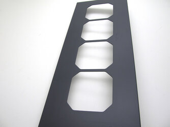
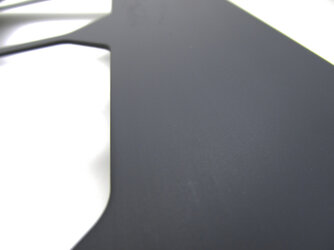
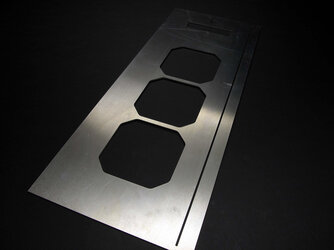
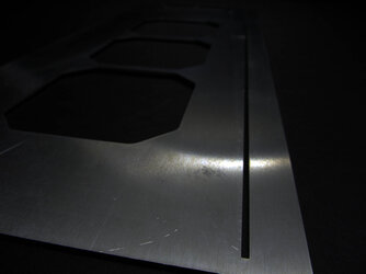
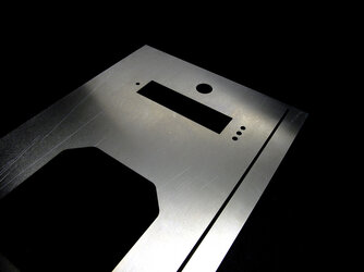
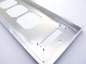
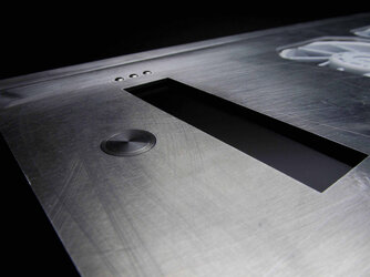
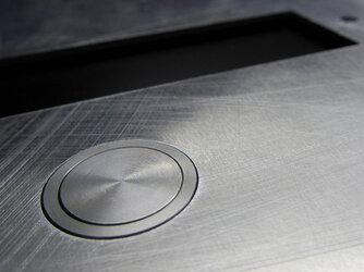
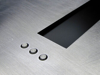
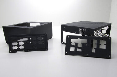
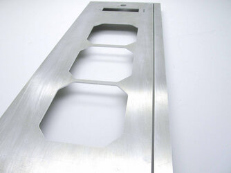
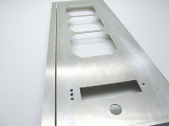
Alright, picking up from the first part I decided that to achieve what I wanted a custom front plate was going to be necessary. My initial plan was to have this new front panel have 4 switch holes for the lights and holes for 4 USB ports along with 3 fan holes, an integrated aquaero 5 pro faceplate and a power switch. However, after some thought I decided to simplify it to a power switch, aquaero 5 pro faceplate and of course the 3 fan holes. I felt the first version was just a bit to busy so removing some of the unnecessary elements hopefully will give it a more sleek look. As a purely aesthetic modification I added a slim strip spanning most of the right side of the panel which will have an acrylic strip (not yet made) back-light with blue LED's. The panel was fabricated out of 0.09" aluminum and was cut via water jet. Below are pictures of the cut aluminum sheet.

Front Plate 1.jpg

Front Plate 2.jpg

Front Plate 3.jpg

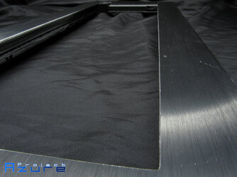
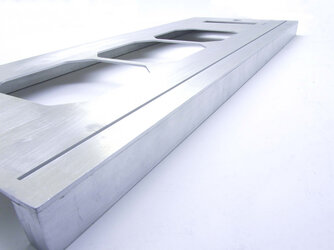
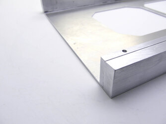
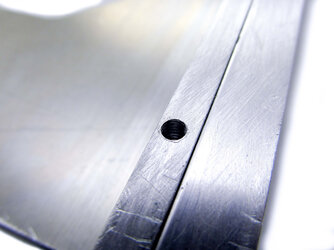
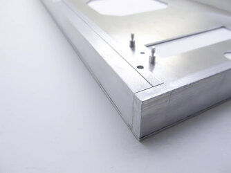
The next task was then to add the thickness to make the actual panel. For this, aluminum bars with a width of 25mm were used which would allow just the perfect amount of clearance for the fans. Unfortunately, due to how far in I needed the screw holes the thickness of bar I needed (16-17mm) was not available so in effort to achieve this thickness I used two bars, one with a thickness of 10mm and a second one which was 6mm thick. The two bars were bonded with high strength glue. This was followed by bonding the bars to the front panel and sanding them down and drilling and tapping the holes for the barbs mounting the front panel to the case (the mounting mechanism is the same as in the stock 700D/800D).

Front Panel 1.jpg

Front Panel 2.jpg

Front Panel 3.jpg

Front Panel 4.jpg

Front Panel 5.jpg

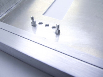
In order to mount the aquaero 5 pro without having screws through the panel I had to bond standoffs to the backside of the panel.

Front Panel 6.jpg

Front Panel 7.jpg

Front Panel 8.jpg

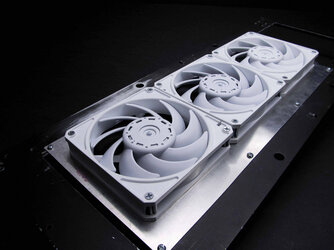
At this point I was interested to see what the piece looked like with the radiator, switch and aquaero 5 installed. There will be an acrylic window that sits in front of the the aquaero 5 display to create a flush look and give some depth to the display, however I have not yet contracted parts out to the laser cutter yet.

Front Panel 9.jpg

Front Panel 10.jpg

Front Panel 11.jpg

Front Panel 12.jpg

Front Panel 13.jpg

Front Panel 14.jpg

Fit is perfect, there is just enough room left for the mesh grills, which unfortunately are not currently ready.

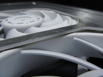
For those interested, here is how the radiator and fans mount to the secondary front panel. The radiator is on the other side of the bracket that is mounted to the secondary front panel.

Front Panel 15.jpg

Since the fans were going to be very close to the front panel normal fan button top screws could not be used as they would prevent the panel from being all the way on it was necessary to have a slightly different way to screw the fans onto the radiator. To get around this I countersunk the fans themselves so screws could sit flush with the fans.

Front Panel 16.jpg

That brings this update to and end.👋
 
beautiful work! wish there was a lazer or water jet cutting place in prince george. alas there is not.

Nice work looking good.


Epic, you should write up something about where you find your supplies. :)

i think a nice fan grill will wrap it up nicely. :)

Thank you all.

Polar, I get my metal from local motor sport shops and the rest typically from McMasterCarr.
 
PSU Modifications

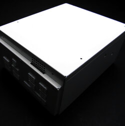
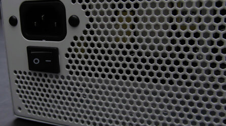
Perhaps not the most exciting update this time around but an update nevertheless. As with the case itself, the PSU will be white and in this instance polished to a mirror finish, partly because I wanted to some practice before doing the exterior. The PSU being used was originally black, so clearly that will need to be the first to go. The stickers were removed quickly followed by the paint.

PSU 1.jpg

PSU 2.jpg

PSU 3.jpg

After the PSU was stripped it was sprayed with self-etching primer followed by sanding primer then finished with a healthy dose of wet sanding until smooth. As I was more focused on getting a quality end product while doing this I did not take pictures of this process and I am not sure they would be overly enlightening even if I had taken pictures, however I may do them for the exterior painting.

PSU 4.jpg

PSU 5.jpg

Next up was painting the PSU with white enamel and a gloss clear coat, which again I do not have pictures of :facepalm:.

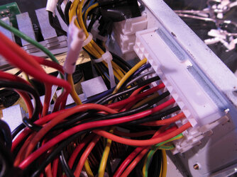
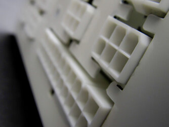
While waiting for the clear coat to dry it was time to work on some other PSU modifications. The first of which was rewiring the PSU to allow for a 1-1 wire match up allowing for straight cables that do not cross all over each other along with eliminating the frustration of sleeving wires that have multiple outputs. First up was to figure out what goes where, then the PSU was then de-pinned, keeping everything organized and then putting the pins where they needed to go. (The PSU was not fully painted here as you can see :-/)

PSU 6.jpg

The re-wiring went very well. No black smoke, all voltages are correct and it even boots a PC! :thup:

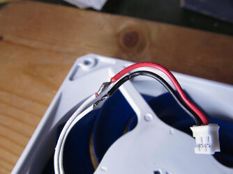
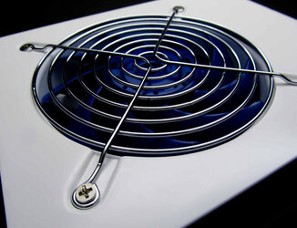
The paint was still not dry yet though! :eh?: So we still have time for more tinkerning. The fan of this PSU is slightly less than quite so why not put in a 1150 RPM GT? This was fairly simple, the PSU fan connector was cut from the original fan and soldered to the GT wires.

PSU 7.jpg

By this point the paint was done drying so it was time for a good deal of wet sanding and polishing.

PSU 8.jpg

PSU 9.jpg

PSU 10.jpg

Of course we must have white connectors for the PSU, and thankfully MOLEX makes actual white connectors.

PSU 11.jpg

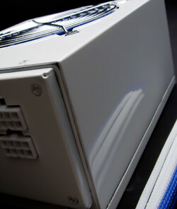
So now the big question, does it have a nice mirror finish? :confused:

PSU 12.jpg

PSU 13.jpg

:attn: It would seem so! It is not quite perfect, but it definitely was a good learning experience and the exterior should be a good deal better. I may redo the PSU, as it does have some minor blemishes, however if I do it at all it will have to wait.
 
Back