• Welcome to Overclockers Forums! Join us to reply in threads, receive reduced ads, and to customize your site experience!

LED circuit Question

Overclockers is supported by our readers. When you click a link to make a purchase, we may earn a commission. Learn More.

Rysjimmy1994

Member
Joined
Sep 11, 2005
Location
Yorkville, IL
So I am trying to make this here LED circuit.
IMG_1182.JPG


They are 32 UV Leds and I keep burning up 18 ohm resistors. They are also 1/4 watts. I am putting 12 volts to it. Should I change the voltage to 5? I really wanted to keep 12 volts, but I guess its not that big of a deal if its not. Any help would be appreciated as usual!
 
they all wired parallel? series? what? whats the forward voltage drop and current rating of them? it might be that 1/4 watt just isnt enough for the resistors, might try putting in a higher wattage one (5 or 10 watts, if you can find one of the right resistance)

you could try droppin to 5 Vs and see how that works.

IR camera project? what it looks like lol.
 
They are all in parallel. I belive the forward voltage drop is 3.6 V and Forward Current is 20mA. I plan on putting this along with another one in my PC case to see how well it will light it up instead of using two CC's.
 
calculators show you'll need at least 5.5 watts, so i say go with a 15 ohm 10 watt resistor. you actually need like 13.125, butim sure 15 will be alot easier to find.

used a online calculator with 12V source, 3.6 v drop, and 640 ma current (32*20=640) and it will give ya the rest. currents are multiplied by number of diodes caus they are in parallel, series would be different.
 
There is no real advantage of me using 12v volts right? I think 5 should be fine I just need to fine a 2.2 ohm 1 watt resisitor
 
i would try the 3.3v rail without a resistor and see how that treats ya ;-)

also, ive seen members turn their PSUs up a little to get more V out of a vdimm mod, they run up to 3.6 volts all the time it seems.

a neat way to tap power for like a 3.3 or -5, -12v lines is...

tin a piece of wire, with 1/4 inch or so of the wire stickin out of insulation and tinned. then jam this down in the back side of the ATX connector, so it wedges between the plugs pin and the plastic wall thing. mine usually stay in fine, but some hot glue can help it too. i ran to the -12V line for quite a while like that (24Vs to a cheap fan will put it to like 1/2 a tornado lol)

also, the aux connector (the AT lookin plug that has a couple 3.3s, grounds and a 5v) can also be a handy source.

just realised i thought you originally said they were ir not uvlol. never mind the ir cam comment lol.
 
if they are all in paralell youre probably drawing over an amp on them. What are their volatages? you should put as much of them in a serise as possible and then paralell the serise connections. Tell me their voltage and current ratings and I can help you out.
 
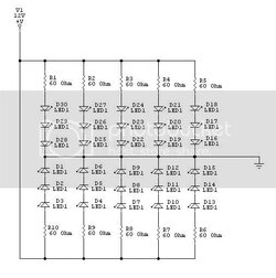
alright if they are 3.6 volt diode the put 3 of them in serise that will create a drop voltage of 10.8volts. @ 20ma. so you will be left with 10 strips of three. the left over leds can be left out or another one added to create an 11th stip. The resistance you will need is as follows
R=E/I (voltage differance over current in amps.)
so 12v -10.8 volts = 1.2 volts @ 20ma.
20ma = .020Amps
so
R=1.2/.020
R=60
so you will need a 60Ohm resistor to drop the voltage to its correct level.
Use a seperate resistor for each strip of 3 leds to prevent burnouts.
You are left with the circuit drawing 200ma of current @ 12 volts. (.020*10) instead of your previous 640ma (.020*32) of current.

here is a schematic i drew up of how to connect them. If you do it this way you will have 2 left over leds. If you have another you could make an 11th strip.
led.jpg
 
Back