• Welcome to Overclockers Forums! Join us to reply in threads, receive reduced ads, and to customize your site experience!

My Chilled Water Cooling Obsession Is Now Version 4.0.

Overclockers is supported by our readers. When you click a link to make a purchase, we may earn a commission. Learn More.
Way, way out of line.

I was just asking a question.

I am just collecting data. How could you possibly see an attack from a mere question?

I have in one way or another been attacked from day one by various individuals for even considering chilled water cooling so for me it is an expected and common thing to happen. My response to you is in my opinion quite tame from my days of old here regarding my attitude, if you don't believe me ask EarthDog, you got the mild version! By the way the very character you chose for an Avatar was always experimenting to improve his inventions, well the fact that I am at version 4.0 and still experimenting, should tell you at least it did not start with this thread. So that's why your opinion does not matter to me it has no bearing on my experimentation.

That said post a link to your cooling and lets see what you run?
I've always been open, maybe you have a better idea, IDK, but if it is just conventional cooling, Been There Done That!

For my own data collection, I would love to see the following numbers:

1. Ambient temperature of the room wherein the chiller is being tested.
2. Average core temperature under full load.
3. Wattage being reported under full load.

That will give me enough information to rate your entire cooling solution.

#1 My ambient room temperature is usually 24c maintained and may vary .5 either way, but ambient room temperature is really irrelevant when you are using a negative DeltaT cooling, meaning 14c below ambient. Ambient does have an effect when it comes to condensation on the outside of the CPU cooling water block, but at a 10c coolant temperature there has been no condensation to be concerned with at all. I do not run motherboard moisture insulation and never have, I operate in a below ambient window, meaning below ambient, but above condensation forming temperatures. That said using traditional ambient calculations to measure efficiency of chilled water cooling is kinda a joke isn't it. Seeing as how it is an active cooling system wouldn't the amount of electrical power being used vs results be a better conclusion to rate a chilled water cooling solution. You must also calculate in the unknown variable, which is the 3rd TEC assembly controlled by the thermal controller that controls the 10c coolant window, meaning the 3rd TEC is not powered all the time, only when needed. That 10c coolant window is cut in at 11c cut out at 9.9c to maintain a 10c operational window. Which is cut in power at 11.0c, active temperature drop, 10.9, 10.8, 10.7, 10.6, 10.5, 10.4, 10.3, 10.2 10.1, 10.0, 9.9c cut out power, which is the 10c operational window and the missing information is the time variable from cut in and cut out. So there are more factors to calculate into the equation besides ambient room temperature.

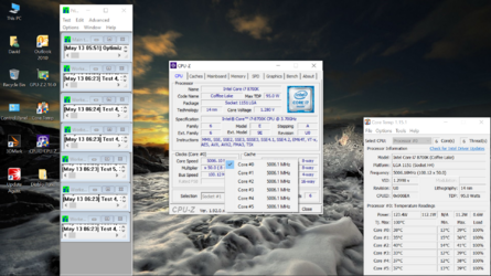
You can get #2 and #3 from the screenshot below, I'm experimenting right now at a 5ghz 8700K overclock running with HT disabled and all 6 cores overclocked, using the least amount of processor voltage possible, which is BIOS set to 1.250v. This is over 30 minutes of Prime95 and Core Temp readings and CPU-Z. Hope this helps! SS
Screenshot (5).png

The screenshot was taken at the maximum electrical and wattage load.
 
Last edited:
This is a cool project. You've taken peltiers to the next level. I only really ever did one complete project with them, and that was 14 years ago in high school. Was on an old school liquid loop and booted at 12C with max load in the low/mid 30s if I remember correctly; I have fever brain right now so who knows. It was a direct mount to the Opteron 165 (!) though, so a lot less complicated. I still have that pelt floating around, and I came across it just a couple of weeks ago when I was looking for an old socket 775 mount I had. Good times.

One of these days I want to turn the bin of phase change stuff I have into a chiller. I think the compressor is still good, it was never used, and all the electronics for it are still in a bag. Perhaps on that day we can have a chill-off and get to frying up some chips!
 
That said post a link to your cooling and lets see what you run?
I've always been open, maybe you have a better idea, IDK, but if it is just conventional cooling, Been There Done That!

I build everything from scratch, including the case. Including the power-on button.

I have a complete build log of the project, from the CAD file to completion, here:

https://www.overclockers.com/forums...syphon-vastly-outperforms-quadruple-radiators

I also have a 30-second video of the 3-stage vapor phase change dual-pump thermosyphon prototype in action.

https://www.overclockers.com/forums...HRQ)-numbers?p=8140928&viewfull=1#post8140928

My only interest in the HRQ was to collect data and see what ranges of numbers were available for EXISTING cooling solutions.
Air coolers should have the lowest ranges. Water coolers next. The Thermosyphon should be higher than water. Then water chillers. Then sub-ambient coolers.

I just wanted to know what the boundaries and ranges of each were. That's all. I stated multiple times this was not a "High Score" thing. The number itself represents what the cooling solution would do if the water block or cold plate was scaled up to one square meter in size.

Interesting projects you're into and it is nice to know there are other experiments going on into cooling CPUs seeing as how it seemed going to lower manufacturing would result in cooler running CPUs but it is quite the opposite today. My experimentation is simply to use less electrical power to accomplish the earlier success of my Chilled Water Cooling and also make it quieter, so I could sit in the same room while using it. I have gone in the opposite direction than many of the peltier cooling active experiments out there, that are determined to use high wattage and high electrical powered peltiers to do the job at their maximum power input. Peltier cooling is not a new idea and neither is the Thermo Siphoning you are into as both cooling approaches need some long term serious refining to get to something tolerable to sit in the same room with. To me your 4,000rpm fans are way too loud to be in the same room with for a long time, so that alone would instantly discourage me from using that cooling, that part of it has to be improved upon. Those type cooling fans are server level fans and there was a good reason most servers were isolated to their own cooling room, because of the noise levels.

Just the fact that I can run Prime 95 and keep the stress test within my 10c coolant window is making forward progress on my chilled water cooling, so I am going in the right direction in my experimentation. However IMO the HRQ idea you seem to base cooling on is irrelevant, to me if it actually works in reality, that is more than proof enough. Seeing as how you disregarded some of what I suggested as variables regarding calculating the HRQ in a Chilled Water Cooling setup using peltiers and a variable thermal load, makes me uncooperative to solving your needs of amusement. Now I have looked over your links and made comments in your threads but I am not a fan of your cooling, but you just do what you do, and more power to your efforts. Maybe one day we'll actually be on common conversational ground, but not today!

That said my cooling approach to using peltiers is working, and my experimentation is to make it better, and better, and better, and maybe one day it can be refined enough to be a viable cooling alternative, or not, but for now it works for me, when it doesn't I'll change it! SS
 
Last edited:
Under MAX load what kind of wattage does the whole system draw? I noticed you said it is all powered off the single PSU, so less than 1250 watts I assume.
 
I To me your 4,000rpm fans are way too loud to be in the same room with for a long time...

Again, that was the first build, total prototype. As stated in the HRQ threads, by using the formula, I determined the CONDENSER was doing most of the cooling. I removed both noisy fans and replaced them with one fan, intentionally missing most of the condenser's surface area, and the observed temperatures rose only 3 degrees C. That told me the condenser was doing most of the heat removal.

So, I replaced it with a SMALLER condenser and 4 smaller fans and... I got the same HRQ number +/- 20 small points. And the fans at 800 RPMs were inaudible.

Just the fact that I can run Prime 95 and keep the stress test within my 10c coolant window is making forward progress on my chilled water cooling...

Which inspired me to add another phase to my cooling solution. Chilled water will cool condensed liquid refrigerant which hits the copper block and vaporizes which enters the condenser cooled by air as the water cycles in a separate loop. The refrigerant will now undergo a greater delta T (which will also guarantee little chance of vapor lock under high heat loads) and therefore should be capable of transporting more heat. How much more is an unknown at this point.
 
Under MAX load what kind of wattage does the whole system draw? I noticed you said it is all powered off the single PSU, so less than 1250 watts I assume.

With all 3 peltiers powered running P95 504W, adding the graphic card load running Firestrike Benchmark, 703W, the power supply is a 1200w single 12v rail power supply. I do have a 4th TEC unit that can be engaged when needed, and it draws 100w by itself, so with it engaged as well at least 800w running load for the entire machine. So the 1200w power supply is only being taxed at 2/3rds it load capability.

Chilled water cooling version 2 pulled a solid 600w just to fully power the peltiers alone, it required a 2nd power supply.

That’s not too bad. I had figured it would have been close to maxing it out.

Sub-ambient cooling and fully stressed for system for 800w. So less than that for normal use pretty cool! :thup:


That’s not too bad. I had figured it would have been close to maxing it out.

Sub-ambient cooling and fully stressed for system for 800w. So less than that for normal use pretty cool! :thup:

It Idles at 283w with 2 peltiers running, maintaining the 10c coolant window the 3rd peltier kicks in for about a minute at 399w and then cuts back out.

I ordered another test power supply this one has variable DC output from 0 ~ 40vdc, the 4th TEC assembly that is my experimental load assist is going to be tested to see how it responds getting more than 12vdc, it is a 24vdc peltier so I am curious to see how different it responds with voltages between 12vdc and say 20vdc. The 4th TEC assembly can either be powered by the main computers power supply or an outside the unit power supply, thus the ability to do the tests. Powering it with the outside unit can get dangerous as it has to be constantly monitored or it will drop the coolant temperature into condensation producing temperatures.
 
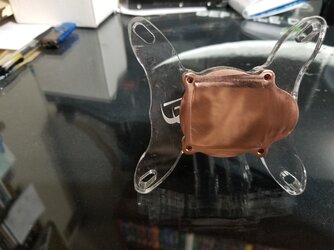
I wanted to cover my CPU cooling water block because it has been modified, the reason for the modifications are simply I was after a water block that was more of the size of the actual heat spreader dimensions, instead of the huge water blocks that have come out lately that hang way past the actual CPUs heat spreader, especially the Intel CPUs.

With chilled water cooling the water block contacting dimensions can be a serious negative regarding condensation if the water block overhangs the actual heat spreader. Because condensation can form underneath the water block and you cannot even see it, until it is too late, even if it is not apparent from the sides of the water block that you can see. The Intel heat spreader size dimensions have been very close to the same size from Sandy Bridge ~ to Coffee Lake +, and having a very large water block is just not necessary, but water block manufacturers tend to make one size fits all water blocks, for AMD and Intel.

In my quest to resolve this dilemma I decided to give and old faithful water block a chance at rebirth, I took and old Danger Den block which was much closer to the size of the Intel heat spreader, but had fell way behind in the cooling of it's day and was discontinued. After thorough examination, I discovered that DD had given the block a lot thicker copper base plate at the contact area than was actually needed, so to start off the modifications I cut approximately 1/32nd of an inch off the bottom of the copper base and then lapped it flat.

I then mounted it using a very small amount of the old cheap white silicon grease to get a contact profile of the base to the Intel heat spreader, then marked out the actual contacting dimensions. Allowing a 16th overlap of the copper base to the heat spreader, I sloped the copper base plate away from the heat spreader contact area, using an assortment of fine tooth steel cutting files, (Not Jewelers Files), standard metal cutting files, and worked carefully to cut away the unnecessary copper on the base to reveal a more feasible contact area to the CPUs heat spreader.

After I was satisfied with the slopes, I meticulously used 600 grit wet/dry automotive paper to lap the slopes, and smooth out the file cuts. It turns out that after these modifications were done to the Danger Den water block it outperformed the cooling performance of the EK Supremacy and the XSPC Raystorm water blocks of the day, not only with chilled water cooling but traditional radiator cooling as well. It is truly a shame we lost the Danger Den contributions to water cooling, Kudos to them! :)

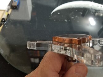
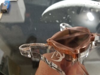
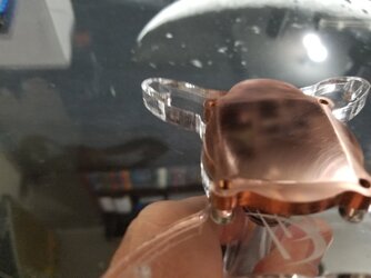
Below are the best pictures I have of the actual modifications to the water block.

Modded Danger Den Waterblock.jpg

Side View.jpg

Mod View.jpg

Most of the pictures don't show just how much the copper is sloped, but the last picture shows it very well!

Best View of the Base Modifications.jpg

I am confident many of you Old School of water cooling recognize this old Danger Den water block! :) SS
 
Last edited:
You going to lap the cpu for better contact as well?

I put a straight edge across the 8700Ks heat spreader and it was surprisingly perfectly flat, so I did not lap it.

I still could, but I don't really think it would help that much, Whoa wait a minute though?

Other than the fact that I could not just lap it but cut some off of it to decrease the thickness of it.

That would be a problem for a regular water block, because lowering the heat spreader height would have the water block contacting the socket clamping frame, but my modded water block wouldn't encounter that problem.

Thanks bmwbaxter!!! :)
 
No problem, glad you used my simple question as a catalyst for more modding. No complaints here :thup:
 
I see this and I'm almost sad that all I did was dig a hole in the back yard and throw some copper tubes in it.
I was thinking that having someone 3D print some sort of water flow "thing" for your blocks might not be a bad idea. Shoot, you could have the whole top of it printed out of PETG or ABS and move the water through it however you wanted.
BTW you're nuts :clap:

EDIT: Remember Ultrasonic2? He's designing nerf guns now. He spent a lot of time on waterflow for his TECs. Maybe he can give you some insight or hook you up with his drawings. Just a thought.
 
Last edited:
Update to vs. 4.1 : Went through a small problem with this setup which forced me to do a redesign, the reason I say small problem is with chilled water cooling accidents will happen, especially if you are the reason it happened. Long story short I had my 3rd peltier assembly on it's own switch that I only enabled during heavy load testing and it was switched on and something happened that got my attention and I left the machine running, unattended. By the time I got back to it I had severe condensation buildup which ran down my water block and dripped right on my Samsung M.2 SSD HDD.

So I redesigned the setup removed the switch, and added 2 temperature controllers to the 2nd and 3rd TEC Assemblies, to be 100% sure that would not ever happen again and so far it has not. The system was down for about 2 weeks while waiting for everything ordered to show up and then it was back in business. Thankfully I only lost the M.2 SSD HDD.

SS
 
Last edited:
After the last issue was resolved posted above over 2 years ago, this setup is still 100% operational I did replace the GPU water cooling pump which took about an hour to do.
Changed my CPU chilled coolant temperature to 13c which is 10c below ambient and it is all working very well. I hope everyone is doing well out there. SS
 
Back