• Welcome to Overclockers Forums! Join us to reply in threads, receive reduced ads, and to customize your site experience!

Boosting PWM signal from Mobo

Overclockers is supported by our readers. When you click a link to make a purchase, we may earn a commission. Learn More.
You gonna need two of Inverted Scmitt Trigger (IST) in series at least.

I had similar idea with yours as well, but my problem is whenever I set my mobo header to 100% and check the output voltage, my DMM shows me around 2.8v.
So I'm kinda stuck at how much volt should I feed to the 555 / 556 with the IST setup :-?

If your mobo header shows something like 3.3v or 5v, then I can say go for it ;)
 
Yes, its possible, infact its quite easy and believe you must have spares 556 lying around there right ? ;)

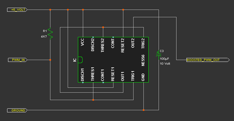
Here, a simple single 556, a resistor and a cap, this cap's value is not very critical as long is 10 volt rated (minimal) from >22 to hundreds of uF, or if you have any non polar cap there like ceramic or plastic, 100nF is enough.

With this simple circuit, I believe it can be built quite small, just becareful on the power lane, it needs 5 volt, so don't connect it by accident to 12 volt rail. :bang head

NE556 as PWM Signal Booster.png

Edit : Forgot to put the R1 which is needed, the value is not that critical as long its above > 1K and under < 10K Ohm.

I'm also BC i dont' want to accidentally fry my motherboard on accident trying this out before I asked lolol :salute:

This is a valid concern, suggesting to try it 1st at your pwm controller output, then use this booster output to test the fan, if it works then you can safely hook it to your mobo fan header at the pwm pin.
 
Last edited:
bing,
is it okay to hook up the 5v IST circuit to my mobo PWM header, when it maxed around 3v while on 100% duty-cycle
 
bing,
is it okay to hook up the 5v IST circuit to my mobo PWM header, when it maxed around 3v while on 100% duty-cycle

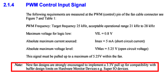
I guess its safe, that 3 volt probably is 3.3 Volt as PWM fan signal standard specification as described in the Intel 4 wires PWM technical specification.

I know this sounds weird, cause this current pwm signal specification is also designed that it will be able to adapt with the future standard which will be using 3.3 volt signal instead of 5 volt like current majority of pwm fans.

Quote from Intel's documentation, I made the red marking regarding this matter.

PWM Fan Signal Spec for Fan.png


Personally I haven't heard of pwm fan that is adapting this new 3.3 volt signal.

So its safe, but again, just test this booster 1st on your controller output, once it worked, I'd say its safe to hook up to the mobo header.

Note : I updated the above circuit, forgot to add the pull up resistor R1 as required by the standard technical specification.
 
Last edited:
haha! Yeah I knew right out that gate when ordering part of Jameco.com that I was undoubtedly going to mess something up so i ordered 5-10 each of what i needed.

I can't stay on those websites for to long man, it's evil, my cart went from like 10bucks with ALL I NEEDED to over 60 by the time I got done browsing around the site....

It got WORSE TODAY, as I found the pF values in the main thread, to modulate the frequency of the timmer(trying to stop my regular analog fans from squealing at low speeds, figured if it works for PWM fans it might help the non-variety)

...I ended up with 390pF and 470pf caps...then came the toolbox for holding all my components, then i stumbled across potentiometers 2k, 5k, short rod 100k's and then i found aluminum knobs that match, and then I found the LM1084IT-ADJ low voltage drop regulators for my Direct Voltage regulator circuit....

I have no self descipline, I'm not allowed in radio shack, or worse, home depot... oOOoo LOOK! BLOWTORCH! GETTIN IT!
 
got the board done (single 555 with 5.1K pull up resistor version and the caps were pulled deliberately from my drawer :p), now gotta work on the cabling....
I wish I won't fry anything :D

u1rf609w8j4lmsn0efxd.jpg
 
I had similar idea with yours as well, but my problem is whenever I set my mobo header to 100% and check the output voltage, my DMM shows me around 2.8v.

aren't you reading "average" volts since the pwm is a square wave? Pretty sure you can't measure voltage of a square wave with a normal DMM. (unless 100% makes it into a steady signal)
 
aren't you reading "average" volts since the pwm is a square wave? Pretty sure you can't measure voltage of a square wave with a normal DMM. (unless 100% makes it into a steady signal)

I was set the PWM to output the 100% duty cycle, so it should show me the "nearly" voltage generated by the mobo header...

I need the Inverted Schmitt Trigger to drive my Delta which is in the inverted mode :)
 
inVain are you sending schematics out to 3rd part for manufacturing or are you fabricating that at home? I thought about making my own pcbs instead of using proto boards but the chemicals needed are dangerous lol I'm not so good with volatile liquids
 
nah,
I'm sending it out to a manufacturer in my city....
I'm really poor at chemicals and afraid that I might hurt myself when mixing those liquor :D
 
Yes, its possible, infact its quite easy and believe you must have spares 556 lying around there right ? ;)

Here, a simple single 556, a resistor and a cap, this cap's value is not very critical as long is 10 volt rated (minimal) from >22 to hundreds of uF, or if you have any non polar cap there like ceramic or plastic, 100nF is enough.

With this simple circuit, I believe it can be built quite small, just becareful on the power lane, it needs 5 volt, so don't connect it by accident to 12 volt rail. :bang head

View attachment 105799

Edit : Forgot to put the R1 which is needed, the value is not that critical as long its above > 1K and under < 10K Ohm.


This is a valid concern, suggesting to try it 1st at your pwm controller output, then use this booster output to test the fan, if it works then you can safely hook it to your mobo fan header at the pwm pin.

Thanks so much for this!

I have 6 Corsair SP120 fans and a pump connected to a swiftech 8-way PWM splitter. The Corsair fans default to maximum speed. PWM would only work for the fans if 4 devices are connected to the splitter.

Followed your schematic and put the amplifier between the mobo header and the 8-way splitter. Works like a charm! Mobo can now perfectly control PWM on all 6 fans + pump.

Pics here

Top
fayhle.jpg

Bottom (pre-hotglue)
2ajbqu.jpg

Bottom (post-hotglue)
fn740x.jpg

All Connected
2pzw3gj.jpg
 
digging this thread up. I built this signal booster and it's not behaving properly. before the pumps would modulate with PWM and the fans would only run at full speed. The fans would periodically flicker from 0% to 100% but mostly stayed at 100%.

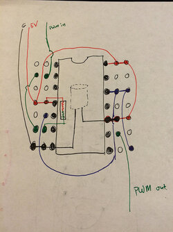
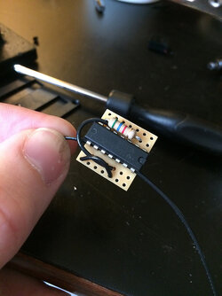
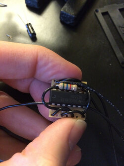
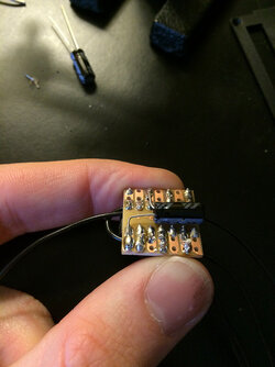
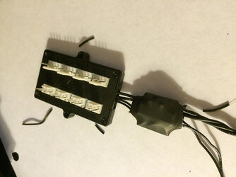
I figured the motherboard isn't generating a strong enough signal so I got cracking on the pwm booster. now everything stays at 0% pwm for any setting except for when it is set to 100% duty cycle. there is no in-between. Here is my build...

15699471864_bfde8d4551_c.jpg
15699468464_3163848b82_z.jpg
16134526230_837d9c3993_z.jpg
15702017633_e39a292bf0_z.jpg
16134509860_e1bfb29eb3_z.jpg

Is this an issue with my motherboard just not generating a coherrant signal or something else?
 
Back