• Welcome to Overclockers Forums! Join us to reply in threads, receive reduced ads, and to customize your site experience!
Fan Controller / PWM Booster / Regulator / Converter / Etc. Thread!

Overclockers is supported by our readers. When you click a link to make a purchase, we may earn a commission. Learn More.
I have actually seen some similar VFDs (though they were Danfoss brand) running the HVAC system in a server room. On one side of the room, there were two air handlers (redundant setup), each with two VFDs. One for the fan motor and one for the compressor. The VFDs were behind a plastic cover so anyone can see how much "reserve" there is on the HVAC but not mess with the settings. There are a few sensors in the racks as part of the control system. One time, someone managed to accidentally disconnect one of the sensors and both VFDs in one of the air handlers immediately detected the fault and went full blast. The room quickly started turning into a walk in refrigerator until the engineer showed up to find and reconnect the sensor.

For a really big inverter, check out what they use in EVs:
http://techno-fandom.org/~hobbit/cars/ginv/i0arrival.html
 
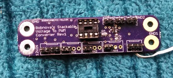
Voltage to PWM boards are more or less done.

Takes a fan voltage type control signal in via the 3pin header, turns it into a PWM output, puts that out (amplified to hell, it'll drive many fans) on the four 4p headers. Tach from 4p #1 is fed through to the 3p input header, for motherboards or other use.
Self-calibrates the 0% and 100% points, so it doesn't matter if your motherboard uses 5v as 0, 0v as 0, or 10v as 0. Ditto for 12, 12.5v, 11v, etc. on the top. Hell your motherboard could use 5.5v as max and 5v as min and it'd figure it out.
Same frequency and invert-output jumpers as the normal PWM controller, but adds a third jumper to reset the calibration.
Calibration is stored in EEPROM, so it remembers between power cycles.

Next version will have a solder jumper to select between normal mode (3p is voltage in, tach out) and pot mode (3p takes a potentiometer, pins are 12v, pot signal, GND), as well as a solder jumper to select between MOSFET amplified PWM out and normal Attiny85 output. Those boards are not here yet.

Designed to be stackable, 12V input via cable to one of the through-hole stacking things, GND via any/all of the others. Right angle headers are needed for stacking closely of course.
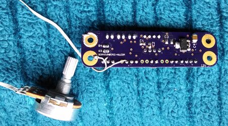
Mounting holes are sized for 4-40 bolts/nuts, and are large enough to solder the bolts/nuts to for permanent installation. You can see one of the GND pads had a nut soldered to it, I pried it off to test how firmly the pad is stuck on the PCB. The solder tore before the pad did.

volt-pwm-r1-top.jpg
volt-pwm-r1-bottom.jpg
 
That turned out nice! Who do you have doing your boards and how much does it cost you for something that size?
 
That turned out nice! Who do you have doing your boards and how much does it cost you for something that size?

Advanced Circuits www.4pcb.com

$14.02 per board x 25, plus I got a $75.00 discount.

For just 1 board, it's $33.00 but as you add more boards, the price drops.
 
Last edited:
Sorry to butt in, but WhitehawkEQ, is that just a standard 555 timer?

I'm trying to wrap my head around this kind of stuff. Did you have to program the chip or something?
 
The discount is a nice plus. I registered over there to check the quotes/pricing out. Looks pretty expensive for less than 100 boards, though it looks like they do have capabilities that Oshpark lacks, plated slots and that sort of thing, I may use them for that at some point.

It is indeed a standard 555 timer, no programming needed. The "programming" is essentially the selection of C2 (which controls the frequency, more or less). Very very simple piece. Also very effective, amazingly so for the simplicity.
 
It switches the ground on and off really fast PWM style. Fine for motors and for brushed fans, not so good for brushless fans.
Brushless fans have a controller built into them that doesn't always appreciate being turned on and off that fast very much.
 
It switches the ground on and off really fast PWM style. Fine for motors and for brushed fans, not so good for brushless fans.
Brushless fans have a controller built into them that doesn't always appreciate being turned on and off that fast very much.

I have another hobby...LED lighting, That controller works very well on and the high speed switching along with POV (persistence of vision) you do not notice the on-off cycles...unless you are watching a fast moving object such as fan blades for example.

I know somethings about circuitry and electronics but not enough to understand all the different topologies. In another words just enough to get myself in deep trouble..:shrug: Problem is I cant reinstall the magic smoke in components.
I have a fan controller but it does not look like it could handle 4 amps of current. It has one power connector and it is a small wire diameter FDD connector. I could change the wire but I doubt the circuit board traces can handle the current.

edit: I hooked it up to power and one of the Delta fans...the transistor got a bit hot and de-soldered itself from the PCB and it is now a dead unit...also the LCD no longer works...
 
Last edited:
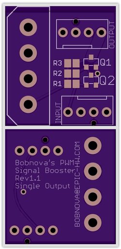
New thing! Slightly modified old thing. More appealing look, smaller size, much lower price.
It's a PWM signal booster just like the other one, but with a single output header. Do the splitting to multiple fans part yourself and save a bunch on initial cost, hide the booster somewhere small.
All the 12v power the fan connector can take is available, and more!

single output rev1.1 pcb.jpg

EDIT:
Didn't see the edit in the above post. Sucks the fan controller died!
 
Last edited:
That voltage control board - does it take a variable voltage input and convert it to pwm? I don't have a voltage driven controller but I'd love to just hook a pot up to one and have it drive a number of pwm fans. Also - if the fan wattage surpasses the board - can i just have the board do pwm and supply the power directly?

Loving the minimalism on these controller boards.
 
Yup, that's exactly what it does. It takes an input voltage and puts out a PWM signal.
The next revision (not ordered yet) has solder jumpers to turn the voltage-signal-in+tach-out port into a potentiometer-in port, so pretty much exactly what you're after.
You can definitely supply power externally/directly and have the board do just PWM.

You can do the same thing with the "standard" fan controller as well, it has solder points to put the pot off-board and have a cable running to the board if you don't want the pot on the board.

I'm also happy to do custom stuff :D
 
Any interest in a serial (or USB) controller for these strips? http://www.adafruit.com/products/1138

60 RGB LEDs per meter, individually addressable 24bit color.
I have two meters, it's really really cool stuff. Amazingly bright.

Evidently, my Z77-HD4 has a serial port! (Though I have observed low voltage from it :-/ )

I also want some LED case lights as well, but I won't lie, I don't eve have Bitcoins to buy with :bang head

But what would be involved?
Like do I need the Audrino like in the pic you linked to?
 
Back