• Welcome to Overclockers Forums! Join us to reply in threads, receive reduced ads, and to customize your site experience!

4 peltier setup

Overclockers is supported by our readers. When you click a link to make a purchase, we may earn a commission. Learn More.
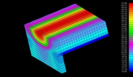
something like this?
avatar2.jpg


you either use an external web uploader, in my case theforumisdown.com or you could use the "Attach file" option that you have when you do a "reply" (not quick reply) to a post (just under option). Also, you could send the file to me and i'll upload it with my account over @ theforumisdown. pm me, i'll give you my e-mail address if you want it.
 
OK here goes, I'm going to try to attach an image. If it is a success I will inclued some explanation.
 

Attachments

  • cube at 10c with 5 tecs 3d cross section.jpg
    cube at 10c with 5 tecs 3d cross section.jpg
    38.1 KB · Views: 386
It worked this time. The image is a cross section of a cube with a temp profile, the scale is on right. The full cube would be 50mm X 50mm X 48mm. The bottom or the side that mounts on the CPU is to the left side and is warmer in the middle. You can see the heat goes up the center and out to the sides as well as the top. Just for the heck of it I put TECs on 5 sides of the cube and set the temp on the cold side of the TECs to 10C, with about 90 watts of heat centered in the last face of the cube. In this case I used Al as opposed to Cu.
 
do you have something similar but for the temperature gradient or "q" if you can have it at one of the TEC face? What I am left wondering is if it wouldn't be better to cool the edge of a rectangle 20x40x40mm with 8 20x20mm TEC and one 40x40mm TEC on top. I mean, it is obvious by the simulation that you made that the temperature gradient in the cube is alot more important at the bottom half than the upper half (for the side face), so a big 40x40mm TEC won't be use very well that way.
In any case, good work with the simulation ;)
 
doc
Interesting
Do you have any values for the Contact Conductances(h) which gives the illustrated profile?
Here have played with crude models for Coldplate/Peltier, using Waterloo to calculate spreading resistance.
Am still very much unsure whether should use "h" of the heatsink.Any thoughts?
 
Prandtl, a cube was easy to do and it has perfect symmerty, I used 5 of the 6 sides with imaginary TECs holding the surfaces at 10C. So what I did here was used the same cube but took off 2 of the TECs on the sides. I'm not sure if I'm answering your question but this was easy to do ( I didn't have to make a totally new model). But anyway the view is the same as before, a cross section of the cube so the temp gradient can be seen inside as well as outside the cube where the TECs have been remove. If this is not what you were getting to let me know and I will make a new model when I get the time.
 

Attachments

  • cross section cube with 2 sides and top being cooled.jpg
    cross section cube with 2 sides and top being cooled.jpg
    39.8 KB · Views: 359
Les56, I'm not sure what you want. h is heat transfer coefficient used for gasses, fluids and sometimes solid to solid contact. They are not writen in stone, so they have a ranges like this:

1 to 30 W/m2 K for free air convection
10 to 100 W/m2 K for forced air convection

If the conditions are different in any cases h will vary. Say for example you polish your heat sink a little more, h might change.
What I do most of the time is ignore h for the first go around unless it is convection of gasses or liquids, then it can be found in a book or online. But for solids there is thermal grease between them aleast in most cases. So I guess I saying I don't have any good numbers for you. My models are simple and are only to show trends at this time. However they can be made more complex, but this requires more starting info as well.
 
yes, that's about it, but can you actually show the heat flux out of a surface? Or how much of the 90W of the heat load goes through each faces and top?
 
Heat flux would be alot harder to do with the software I am using. Instead of telling you what the flux is, you set up the conditions for a dT, and see if the temp is what you need it to be. However the heat flux will be proportional to dT at any point on the surface. But as you drawing heat from that area the temp will drop proportionally to the heat that is removed from that area. Not an easy problem to solve. So my answer is no, but if you have a specific model you would like to try, let me know and I will see what I can do.
 
I will do a Cu based model, but I can guess at the outcome already. The temp at the heat source will be a little cooler. The only change will be the themal conductivity, the trend or look of the model will be the same, just different temps. What modeling is good for is to see what happens when you change geometries or things like that.
 
doc said:
I will do a Cu based model, but I can guess at the outcome already. The temp at the heat source will be a little cooler. The only change will be the themal conductivity, the trend or look of the model will be the same, just different temps. What modeling is good for is to see what happens when you change geometries or things like that.

I see. This modeling thing is interesting. What is the software called that you use?
 
The software that I use is called TAS, which is short for Thermal Analysis Software. This was developed by Harvard Thermal Inc., they can be found at harvardthermal.com. I use TAS in my job frequently and do a few jobs on the side with it. I am using version 4, I think they are up to 6 now. Version 4 cost about $2500, I dont know what 5 or 6 cost, have not looked at the cost lately. So if you have something of interest let know.
 
Four Peltier Setup

I have thought about using four peltiers also.

The only thing that really stops me is the power consumption.

The power consumption for the two 172 watt peltiers I currently use is high enough!

My cold plate is around 42mm x 90mm and has two peltiers mounted on it. Each peltier is 40mm x 40mm in size.

My website: http://www.e-magic.co.nz/starlet/

To mount four peltiers I thought an "inverted T" shaped, thick, copper coldplate would be best. That is with two peltiers on each side of the vertical part of the T cold plate and a water block on each pair of peltiers.

Serious power consumption and bulk though. It would also need a huge radiator/fan setup too. I think the next step will be phase change for me. A Prometia Mach II looks too good to resist when the funds allow. :D
 
I modeled your inverted T cold plate for 2 40mm X 40mm TECs to show the trend and I had done this before. I asumed that all surfaces not used by the TECs or CPU would be insulated, therefore no heat flux. I made the TECs mount 24mm X 40mm X 40mm and the base plate 50mm X 50mm X 4mm, then cross sectioned it to see the heat flow and temps. This is what I have.
 

Attachments

  • t type coldplate for 2 tecs cross section.jpg
    t type coldplate for 2 tecs cross section.jpg
    55.8 KB · Views: 60
I redid the model but with 2 20mm X 20mm TECs on top. In both images (above and below) the TECs are holding the surface temp at 10C. This is what I got.
 

Attachments

  • t type coldplate for 2 tecs cross section 2 tecs on top.jpg
    t type coldplate for 2 tecs cross section 2 tecs on top.jpg
    48.6 KB · Views: 58
Back