• Welcome to Overclockers Forums! Join us to reply in threads, receive reduced ads, and to customize your site experience!

Asus P4C800-E VCore Voltage Variances Revealed

Overclockers is supported by our readers. When you click a link to make a purchase, we may earn a commission. Learn More.
BIOS ver 1014

Total number of readouts: 3061
CPU Speed: 3747 MHz
Running from: 12/01/2004 00:27:17 until: 12/01/2004 08:58:53
Sensor.......Current.......Low.........High........Average
Case............21° C.......18° C......23° C.........20° C
CPU.............30° C.......27° C......42° C.........38° C
Core 0.........1.86 V......1.68 V.....1.87 V.......1.75 V
Core 1.........3.17 V......3.12 V.....3.18 V.......3.15 V
+3.3............3.30 V......3.15 V.....3.39 V.......3.27 V
+5.00..........5.05 V......4.97 V.....5.11 V.......5.05 V
+12.00.......12.03 V....11.90 V...12.10 V.....12.00 V

M.
 
Last edited:
I have this same problem. I posted here.

Have you had any success with the mod? I am rather convinced this voltage dip under load is limiting my o/c.

I'm a 1.6v now (I've been to 1.725 trying to keep the load voltage above 1.6--to no avail). Under load it bottoms out around 1.552. I don't think it is PSU problem. I've got an Antec True480.
 
I've done the droop mod successfully. Feel free to ask any questions you like.
 
Polargoat said:
has it fixed the problem? anymore drastic fluctuations? How hard was it to do on a scale of 1-10?

It sure did. No more drastic fluctuations. It was freaking hard. The cap you have to solder the resistor to is so rediculously small... bah! It was at least a 9, probably a 10, in terms of difficulty IMO... but it did fix the problem.
 
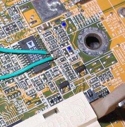
I too did the droop mod. However, a much easier way to do the same mod is to use two safer alternate solder points rather than across the usual capacitor . Discovered by "Macci", using these two points electrically amounts to the same thing. The link to the procedure is at:

http://www.xtremesystems.org/forums/showthread.php?threadid=26902

I soldered a variable resistor to the two "blue" points and found that 47000 ohms was the exact resistance that reduced the voltage fluctuation (idle-load) to .05 volts, a value I consider acceptable. [email protected], 1.58volts@load using CPU Burn-in. I replaced the variable with a permanent 43k resistor to have a 10% margin. The response to lowering the resistance further is very slow and probably using a 33k resistor would guarantee good results without any risk or adjustments. Much easier than soldering a variable across a capacitor...Mark
 

Attachments

  • droop2.jpg
    droop2.jpg
    57.2 KB · Views: 979
Last edited:
Man, I wish Macci had pointed that out before I did the mod!

Here's what mine looks like:

droop.jpg


You can't see the soldering point, but you get the idea of what it looks like.
 
"for the alternative points, which one goes to ground on the pot?"

Don't use a pot! Just solder a 33k resistor and all will be well.
 
Uhhhh, the later models of the PIV are DESIGNED by Intel to do just this. Voltage is SUPPOSED to drop as the load increases.

Look at the Intel technical documents for the Northwood and Prescott PIVs.
 
True, and every board reports that it does drop when under load. But with this board, it drops by a relatively large amount. The modification doesn't get rid of the voltage drop, it just lessens it to a "more reasonable" level for overclocking purposes. People are reaching higher stable overclocks by doing this mod... the results speak for themselves, whether it is supposed to drop under load or not.
 
I have exactly the same readings as Thumper. That's why I had some problems with stability in benchmarks. The performance using 3299 clock (1,502 Load <>1,552 Idle) was worse then using 3000 clock (1,52 Load <>1,552 Idle). Do you know if using 3GHz CPU on this mobo you should have 3055 clock or only 3000Mhz? It seemd to me that it was 3055 on my mobo, but after some unsuccesfull overclocking and going back to standard settings it changed to 3000MHz. Amazing! :mad:
 
Back