• Welcome to Overclockers Forums! Join us to reply in threads, receive reduced ads, and to customize your site experience!

FEATURED Building PWM Controller for 4 wires PWM fan

Overclockers is supported by our readers. When you click a link to make a purchase, we may earn a commission. Learn More.
Interesting, So I added a pull-up resistor of 15K. Fixed it. I now have control of the TFC1212DE by motherboard PWM. Next step is to make a small version of the inverter and find a place to put them. Also decide if i dare get a second and use them as my CPU's fans.


glad you made it :thup:

ummmmm,
I really don't know what's the difference between the G06 vs G01 :D

my best bet, they were a revision number. maybe :shrug:
but, I got 4 of this SanAce.
3 of them were ended up with G03, while the other one was G06 as can be seen on the picture.
two of the G03 were made in the Philippine, and one of them was made in Japan.
the interesting part is, with the very same controller; one of the G03 which made in the Philippine can be run @1200rpm without breaking my noise tolerances.
while the other G03 which also was made in the Philippine only can be run <700rpm. beyond that, this fan's quite annoying to me.
as for the last G03 which made in Japan, I can only run it @900rpm before it breaks my limit.

as for the G06, it mostly spend its time within the closet as I haven't really try it for anything :chair:
 
so it just happen after I build my latest controller with the SMT components.
I've got 555 chips with no clear pin #1 identification.
identifying the pin was a really pain, since I got to measure resistance and compare it with the other 555 with a clear mark on itself.

What is the part# on that chip? I'll look it up and tell you where pin 1 is
.
 
What is the part# on that chip? I'll look it up and tell you where pin 1 is
.

uuuummmmm.....
I'm not quite sure, so I just upload the picture of the chip instead :chair:

View attachment 147531

fyi, the bottom side of the chip were also plain, no marking at all :shrug:

since there's no exploding chip and all the controllers work okay, so I just called it a day with orienting the chip that way :D


silly me,
just remember still have few of this chips in my bin.
here's a close up of a single unused unit:
View attachment 147532
 
Last edited:
uuuummmmm.....
I'm not quite sure, so I just upload the picture of the chip instead :chair:

View attachment 147531

fyi, the bottom side of the chip were also plain, no marking at all :shrug:

since there's no exploding chip and all the controllers work okay, so I just called it a day with orienting the chip that way :D


silly me,
just remember still have few of this chips in my bin.
here's a close up of a single unused unit:
View attachment 147532

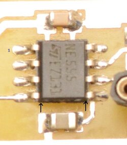
Place the chip so that you can read what in on it, pin 1 will be in lower left cornner, like so:
View attachment 147543

There is always a way to know where pin 1 is on any chip, if you can get the data sheets for it and that will show where pin 1 is. And yes you did get that chip in right place on that board :) :thup:
Also, I noticed that the side with pin 1 is beveled more than other side.
 
My 9SG1212P1G01 gets noticeable around 1.1K RPM. Due to the aluminum frame, it resonates at certain frequencies and is very loud only at certain speeds.

I wish my stupid EFC1212DE's were PWM
 
Last edited:
Place the chip so that you can read what in on it, pin 1 will be in lower left cornner, like so:
View attachment 147543

There is always a way to know where pin 1 is on any chip, if you can get the data sheets for it and that will show where pin 1 is. And yes you did get that chip in right place on that board :) :thup:
Also, I noticed that the side with pin 1 is beveled more than other side.

how did you do that :shock:
been trying to figure out what you've posted for this whole day, but I still can't tell which one's pin #1 only by looking at the chip :rain:

I guess, I'm just lucky with that chip :chair:


My 9SG1212P1G01 gets noticeable around 1.1K RPM. Due to the aluminum frame, it resonates at certain frequencies and is very loud only at certain speeds.

I wish my stupid EFC1212DE's were PWM


oh, I forgot to tell you.
I mount the fan on a self made rubber pads.
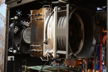
and for the fan which was able to run @1200rpm, I need to run it with a shroud (formerly an EFB1212VHE :D) on the intake.
using a pad on each corner as well.

DSC_0763.JPG

it doing its job really well that way
 
In order for that shroud to be effective, you need it between the fan and the heatsink.

Actually... is it just me or is that whole orientation of fans not correct? It looks like the rear fan is blowing IN the case, while the fan on the heatsink is blowing through the heatsink to the back of the case.... where it runs into that other fan blowing right back at it.

Either way its blowing, that shroud is useless in its current position. It should be (when looking at the picture Fan->Shroud->HS regardless of airflow direction. As I said, the shroud should be in between the fan and HS.
 
Last edited:
yes, you're right.
the shroud should be in between the fan and the HSF to help eliminating the dead spot created by the fan hub.
but in my case, I really need the shroud to be placed on the intake to help reducing the noise.
it really not an ideal solution, really.
but at least, it works for me.
the shroud should be replaced with inlets to help directing the airflow to the fan.

I think, the PAPST will describe this matter better than I do.
you can read it here:
http://www.ebmpapst.com/en/products/product-news/flowgrid/flowgrid.html

been tried placing a shroud in between the fan a the HSF, but I don't feel comfortable with the additional noise :D


as for the rear fan,
it actually blowing outward, outside the case.
the fan is rotating counter clockwise, and the frame was deliberately designed as is.
but by having the frame like that, the fan really doesn't introduce any noise when it placed close to the grill at the intake (I have another fan as an intake on the bottom of my case)
and this is the exhaust side of the fan:
14828625993_2b58d223f2_c.jpg


in either way, I believe this post will describe the fan better:
http://www.overclockers.com/forums/showpost.php?p=7337586&postcount=194
 
Ahhhhhhhhh, a backwards fan blade orientation and the shroud not being used in a typical fashion... got it now! :)
 
Last edited:
yep, you sum them up nice and tidy :thup:

it's really my own fault since I'm messing around with fans that were not intended to be used inside a PC anyway.
so I'm afraid the solutions were also a "weird" ones :D
 
how did you do that :shock:
been trying to figure out what you've posted for this whole day, but I still can't tell which one's pin #1 only by looking at the chip :rain:

I guess, I'm just lucky with that chip :chair:

Well, I'm a electronic Tech and worked in electronic manufacturing for 10 years.
Look at where the arrows are, 1 side is angled more than the other side.
Also, see where the ST logo is, the pin next to that is pin 1.
DSC_0738.555.JPG

Also look at this from a data sheet:
555-DS.JPG

Oh, what do you call an upside down IC?


A dead bug :rofl:
 
Last edited:
IC :D

I suppose, this is what you meant when you said;
"Also, I noticed that the side with pin 1 is beveled more than other side."

View attachment 147610

thanks for clear things up.
it's always nice to have experts sharing their experiences.
much appreciated for you help :thup:

but, in the end I'm still gonna say;
what a sharp eyes you've got there :attn:

Yep, as for sharp eyes I don't know about that :) it's just knowing what to look for, it all comes down to training and experience. Remember, there is always a way to tell where pin 1 is on any chip. :thup:
 
The fact that you don't have globs of solder everywhere proves that I am a sh*tty with a soldering gun. Let alone a blow torch lol.
Nice job :thup:
 
progress been slooowwwwww at the moment.
just manage to do some fit testing, hope will get it soldered soon :D

View attachment 148449

for a hand job (pun intended :p), I'm pretty much pleased with the result
 
I should have mentioned this before. If anyone makes one of mine, I'd recommend plugging your system fan into the motherboard cpu fan header. Some motherboards will dead stop if they don't register a fan on the cpu. Alternatively, you can disable the resistor pullup on the rpm line and splice the cable down to your motherboard header on a 3 pin fan connector, and put a 10k resistor between the power and ground on that fan connector.... should work at providing an rpm to the controller and the motherboard at the same time. Do that at your own risk though.... safer to just plug a system fan into the cpu header on the motherboard and isolate your cpu fan to the controller.

The circuit boards are designed to be populated, then soldered directly to a pin header row that is soldered to the 16x2 lcd. You have to be careful not to get that pin alignment backwards. Otherwise, book lcd. Standard 16x2 lcd should work fine. It makes the lcd face one direction, and as in my pictures, the board face out. This is why you need to populate and test the board before you hook it to the lcd. Otherwise you will find yourself chasing rats with a board you can no longer do soldering work on because it is attached directly to an lcd. A simple solution is to solder a pin header into the board, then plug that into a breadboard. On the breadboard, have another 16x2 lcd with a pin header soldered to it ready for testing. Plug them both into the breadboard making sure you have the pin alignment correct so as to not have the connections backwards. After you've verified all is well, you simply solder a fresh new 16x2 lcd onto the pins sticking out of your populated circuit board.

Don't forget to use a dip socket on the circuit board. Directly soldering the pic16f818 chips is chip suicide.

MOST motherboards will dead stop if they don't register a fan on the CPU header. But I would not use a resistor on that third pin. Any 3 pin fan located anywhere in the case can connect to the PWM CPU fan header and fix this problem. Fix number two: I use a 1.3 amp Delta fan on my CPU cooler. This fan's amperage exceeds the CPU fan header's one amp limit, but I still wanted to use the PWM fan speed control on the CPU fan header. This is easy to do. Pull pins 1 & 2 from the fan plug, and connect them directly to the power supply through a IDE Molex connector. Then connect pins 3 & 4 to the CPU fan header on the main board. This type of connection has the highest limit; it’s normally limited only by the wire gauge of the connecting wire. There are adaptors available that can make this same connection. With a connection like this, the PWM CPU fan header can control several fans.

2000


Never exceed the CPU fan header's one amp limit. if the fan's needs exceed the current capacity of the circuit, the limiting (weakest) part of the circuit will overheat. Our fan's speed is controlled in two ways "voltage pulse duration" or " amount of voltage". The current should never be limited, the fan should always be provided with access to what ever it needs.
 
Last edited:
Never exceed the CPU fan header's one amp limit. if the fan's needs exceed the current capacity of the circuit, the limiting (weakest) part of the circuit will overheat. Our fan's speed is controlled in two ways "voltage pulse duration" or " amount of voltage". The current should never be limited, the fan should always be provided with access to what ever it needs.

hi Luke,
welcome to the forum :welcome:

Jason has build his own version of pwm fan controller based on this thread.
I personally too, rather not to mess with my motherboard and leave it as is
but I'm no good when it come to the MCU things :D
I hope Jason will drop by to clarify things for you


I'm just guessing, but I think this thread have a contribution for that swiftechs' PWM splitter :chair:
and I'm sure lots of us in this thread have built something similar with the swiftech.
such I am.
and here's mine:

View attachment 148832

I hope those capacitors would provide a little extra stability for the power supplied to the fans after traveling a long distance on the molex peripheral wires, but what do you think about it? was it overkill to have those caps?


thanks to bing who shared his design and Brutal-Force who started this thread, we manage to create a controller that send a signal to the 4th control line of our pwm fans.
thus, allow us to achieve full sweep of our fans rpm range and keep our power consumptions efficient.

yes, extreme cautious should be taken on the connectors and cables we choose to feed the supply to our power hungry fans :salute:
 
Back