- Joined
- Nov 25, 2001
- Location
- Niagara Falls, Ontario, Canada
Hey guys,
I've been searching for how to do this for months. I finally got down and dirty with the Intel tech docs and figured it out myself. There is very little information about this on these forums or out on the web, so I'm writing this post as a reference for anyone else trying to do this, hopefully it will get linked or added to the sticky.
What this does.
On a 100Mhz capable motherboard with no FSB jumper this will allow a 66Mhz PPGA or FCPGA socket 370 CPU to run at 100Mhz where simple pin taping will not work. It would be best to test your CPU at 100Mhz on a more friendly board before doing this mod. PPGA celerons max out at 600Mhz, most a bit below that, and FCPGA celerons max out at around 1 Ghz I think, probably more like 900Mhz for the 66Mhz bus ones. This should work for all mendocino and coppermine celerons with a 66Mhz default bus. Check the overclockers CPU database for the likelihood of success with your CPU at www.cpudatabase.com
Why I did it.
I got given a free IBM netvista case and mobo, and somehow in my infinite wisdom promised it to someone who fell in love with it's neat small form factor blackness "when I've fixed it up" before I'd checked it out. This person only needs it really for webbrowsing and mail, but I consider 500Mhz to be the "pain point" for systems to do this these days. To stream video or watch DVDs 500Mhz seems the least you want to consider. Since this is a charity case, and I'm not greatly wealthy, I didn't want to shell out $50 or so for a 1Ghz PIII or FCPGA celly to go in it, so I had to make do with what I could find for cheap. I did get hold of a Tualatin, but then discovered this mobo didn't natively support FCPGA2, and had the wrong i810 revision to be sucessfully modded with that. That left me with a 366 PPGA celly.....
What didn't work.
I tried firstly to merely insulate the BSEL pin AJ33 ( BSEL0 on FCPGA ) as works on SLOT 1 CPUs or slotkets as the B21 mod. I tried this by painting the pin, which scraped off, by sliding insulation over it, which stripped, and finally by taping the contact inside the socket. I guess this is a bit of a brutal socket since it managed to defeat 2 types of insulation. Anyway, insulating the pin did nothing on this i810 S370 mobo. Since we need a logical high on the BSEL pin, and it didn't seem to float high, I next tried "wire trick"ing it between the BSEL and VCC, which with this CPU is 2V. This didn't work, but having a brutal socket, which I thought was causing problems with that, I tried solder bridging it instead. This made full contact, but .... The board refused to POST, gave me a beep code for a memory error. Most odd. So I undid it, and we were back to the pedestrian 66Mhz again. So I went looking for the tech docs, and found the Celeron PPGA/FCPGA data sheet....
ftp://download.intel.com/design/celeron/datashts/24365820.pdf
Reading that told me that logical high for the BSEL pins was 2.5 Volts, hmmm maybe 440BX boards are more tolerant of a lower pullup, maybe it's this particular i810E motherboard, but I thought I ought to try and do it in spec....
What Worked.
I already had AJ33 the BSEL (0) pin insulated inside the socket when I tried this. According to the data sheet the BSEL pins need a 2.5V logic high pulled up through a 10 kilo-ohm resistor. So I went looking for a 2.5 source and found it on pin Z36 . Hunting through my components stash snagged me a 10K resistor, so all that needed doing was to solder it between AJ33 and Z36 on the back of the mobo right? RIGHT! On the initial boot, I though I had failed again because BIOS was showing the CPU as a 366@66Mhz However, I booted a floppy with HWINFO on, an excellent DOS system info tool with CPU information and benchmarks, and it was running @ 100Mhz and benched as fast as a 550Mhz CPU should, w00t!!! On previous tries with the pin insulation I had also done this to check and seen it at 366/66Mhz still.
What you need to do this.
ANY MODS TO YOUR HARDWARE ARE DONE AT YOUR OWN RISK
Soldering iron with a small tip
Thin electronic solder
10Kilo-Ohm resistor. Colour code is Brown Black Orange, numeric code is 103
Tape
Steady hands!
Marker pen.
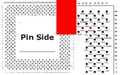
Firstly refer to the picture attached. The pins you need to solder the resistor to are marked in red, this is a pinside view of the CPU, and what the socket pins look like from underneath your mobo. Use a marker to indicate the pins you will solder to. When your iron is nice and hot put a little extra solder on each pin, shape your resistor leads to contact each pin. Insulate the spare lead on the resistor if necessary to prevent shorts to other pins. Add a dab of solder to each end of the resistor. Then tack her in place with the soldering iron. Be sure to hold the soldering iron on the joint as briefly as possible in order not to fry anything on your motherboard. Tape over the resistor with insulating tape so it is neither knocked off accidentally nor fouls or shorts the motherboard tray. Next flip over the board, and carefully unclip the top slider from the socket. locate AJ33 from above (remember it is flipped from the pinside view) insert a small strip of tape over the contact inside the socket to insulate it from the CPU. Put the socket back together. All done, you should now have a motherboard that is locked at 100Mhz and will run any 66Mhz CPU at 100Mhz. (Provided it will overclock that far) if it needs a little help, search for vid pin mods to up the core voltage, there's plenty of info around on those.
Hope someone finds this info useful, use at own risk,
regards,
Road Warrior
I've been searching for how to do this for months. I finally got down and dirty with the Intel tech docs and figured it out myself. There is very little information about this on these forums or out on the web, so I'm writing this post as a reference for anyone else trying to do this, hopefully it will get linked or added to the sticky.
What this does.
On a 100Mhz capable motherboard with no FSB jumper this will allow a 66Mhz PPGA or FCPGA socket 370 CPU to run at 100Mhz where simple pin taping will not work. It would be best to test your CPU at 100Mhz on a more friendly board before doing this mod. PPGA celerons max out at 600Mhz, most a bit below that, and FCPGA celerons max out at around 1 Ghz I think, probably more like 900Mhz for the 66Mhz bus ones. This should work for all mendocino and coppermine celerons with a 66Mhz default bus. Check the overclockers CPU database for the likelihood of success with your CPU at www.cpudatabase.com
Why I did it.
I got given a free IBM netvista case and mobo, and somehow in my infinite wisdom promised it to someone who fell in love with it's neat small form factor blackness "when I've fixed it up" before I'd checked it out. This person only needs it really for webbrowsing and mail, but I consider 500Mhz to be the "pain point" for systems to do this these days. To stream video or watch DVDs 500Mhz seems the least you want to consider. Since this is a charity case, and I'm not greatly wealthy, I didn't want to shell out $50 or so for a 1Ghz PIII or FCPGA celly to go in it, so I had to make do with what I could find for cheap. I did get hold of a Tualatin, but then discovered this mobo didn't natively support FCPGA2, and had the wrong i810 revision to be sucessfully modded with that. That left me with a 366 PPGA celly.....
What didn't work.
I tried firstly to merely insulate the BSEL pin AJ33 ( BSEL0 on FCPGA ) as works on SLOT 1 CPUs or slotkets as the B21 mod. I tried this by painting the pin, which scraped off, by sliding insulation over it, which stripped, and finally by taping the contact inside the socket. I guess this is a bit of a brutal socket since it managed to defeat 2 types of insulation. Anyway, insulating the pin did nothing on this i810 S370 mobo. Since we need a logical high on the BSEL pin, and it didn't seem to float high, I next tried "wire trick"ing it between the BSEL and VCC, which with this CPU is 2V. This didn't work, but having a brutal socket, which I thought was causing problems with that, I tried solder bridging it instead. This made full contact, but .... The board refused to POST, gave me a beep code for a memory error. Most odd. So I undid it, and we were back to the pedestrian 66Mhz again. So I went looking for the tech docs, and found the Celeron PPGA/FCPGA data sheet....
ftp://download.intel.com/design/celeron/datashts/24365820.pdf
Reading that told me that logical high for the BSEL pins was 2.5 Volts, hmmm maybe 440BX boards are more tolerant of a lower pullup, maybe it's this particular i810E motherboard, but I thought I ought to try and do it in spec....
What Worked.
I already had AJ33 the BSEL (0) pin insulated inside the socket when I tried this. According to the data sheet the BSEL pins need a 2.5V logic high pulled up through a 10 kilo-ohm resistor. So I went looking for a 2.5 source and found it on pin Z36 . Hunting through my components stash snagged me a 10K resistor, so all that needed doing was to solder it between AJ33 and Z36 on the back of the mobo right? RIGHT! On the initial boot, I though I had failed again because BIOS was showing the CPU as a 366@66Mhz
However, I booted a floppy with HWINFO on, an excellent DOS system info tool with CPU information and benchmarks, and it was running @ 100Mhz and benched as fast as a 550Mhz CPU should, w00t!!! On previous tries with the pin insulation I had also done this to check and seen it at 366/66Mhz still.What you need to do this.
ANY MODS TO YOUR HARDWARE ARE DONE AT YOUR OWN RISK
Soldering iron with a small tip
Thin electronic solder
10Kilo-Ohm resistor. Colour code is Brown Black Orange, numeric code is 103
Tape
Steady hands!
Marker pen.
Firstly refer to the picture attached. The pins you need to solder the resistor to are marked in red, this is a pinside view of the CPU, and what the socket pins look like from underneath your mobo. Use a marker to indicate the pins you will solder to. When your iron is nice and hot put a little extra solder on each pin, shape your resistor leads to contact each pin. Insulate the spare lead on the resistor if necessary to prevent shorts to other pins. Add a dab of solder to each end of the resistor. Then tack her in place with the soldering iron. Be sure to hold the soldering iron on the joint as briefly as possible in order not to fry anything on your motherboard. Tape over the resistor with insulating tape so it is neither knocked off accidentally nor fouls or shorts the motherboard tray. Next flip over the board, and carefully unclip the top slider from the socket. locate AJ33 from above (remember it is flipped from the pinside view) insert a small strip of tape over the contact inside the socket to insulate it from the CPU. Put the socket back together. All done, you should now have a motherboard that is locked at 100Mhz and will run any 66Mhz CPU at 100Mhz. (Provided it will overclock that far) if it needs a little help, search for vid pin mods to up the core voltage, there's plenty of info around on those.
Hope someone finds this info useful, use at own risk,
regards,
Road Warrior