• Welcome to Overclockers Forums! Join us to reply in threads, receive reduced ads, and to customize your site experience!

Project: Haxor-Jr.

Overclockers is supported by our readers. When you click a link to make a purchase, we may earn a commission. Learn More.
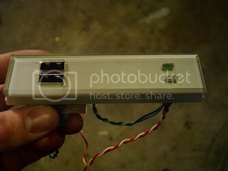
I then used some "red plunger" epoxy to secure the LEDs and the USB ports. I had to trim some of the outside edges of the USB ports to make it fit, but it's like a glove now. :)

cover_finished2.jpg

cover_finished1.jpg

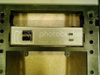
After letting the epoxy dry, I went to put it in the 3.5" cut out in the front panel, to be sure everything looked okay. I noticed the cover wouldn't slide all the way into place, and there was a gap along the bottom. Just enough to stop me from putting the floppy drive in above it.

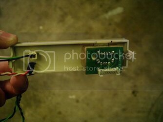
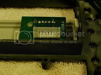
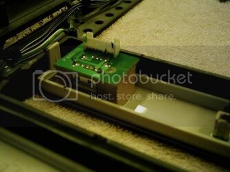
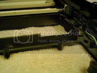
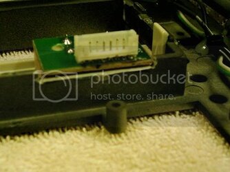
Turns out I had missed one little thing....The printed circuit board (PCB) hung out down the bottom just enough to give me trouble, and running into a lip in the back of the 3.5" cut out on the front panel!

cut_notch_before1.jpg

cut_notch_before2.jpg


The gap:
gap.jpg
 
Last edited:
I had already put the flex shaft and everything away, in hopes that everything would be perfect, but no....So I pulled the Dremel out, and decided to try out the right angle adapter attachment my dad has. It worked spectacularly, and it's pretty much a perfect fit.

cut_notch_after1.jpg

cut_notch_after2.jpg


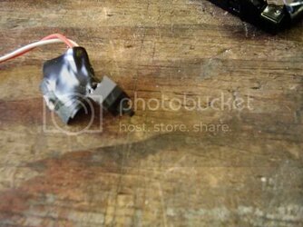
I'm hoping to put the power switch between the LEDs and the USB ports, but I'm not sure how, or what kind of switch I should use. I originally had planned to use the typical ATX switch, also used for reset buttons, but I wasn't sure how to secure it to the bay cover. I cut down the end of the switch and made a small square button to glue to it, but I'm not sure if I really want to use it yet, since cutting the holes in that bay cover isn't the easiest thing to do.

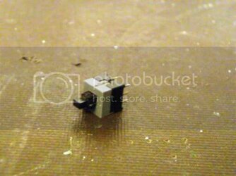
Here's the switch I was planning to use:
power_switch1.jpg


I'll be posting pictures of the waxed CD-ROM covers and the power supply as well. Right now, I need to get some studying done and then I leave to work.
 
Last edited:
Sorry about forgetting!!!!

I totally forgot to post pictures Wednesday night (5-4-05), and I'm very sorry about it. We've lost 1/3 of our staff at work in the past two weeks, so I've been staying late until they can cover the closer's shifts.

I left these photos their default size, because I think the paintjobs on these things deserve the respect, and showing off of detail. Also to keep those of you on 56k from getting bogged down with 5.6MB of digital camera images.

Sorry about blurry pictures. I will take new ones of the assembled drives soon, which I promise will be clearer.

Anyhow, I did get pictures taken of the optical drive's paintjobs after they were waxed with some Meguiars #26 Hi-Tech Yellow Paste Wax. I'd love to get my hands on a tin of #16 though!!!

The Wax
http://i6.photobucket.com/albums/y203/virax3/Haxor-Jr/HI_Tech_Yellow_Wax.jpg


Verbatim 52x CD-RW Drive
http://i6.photobucket.com/albums/y203/virax3/Haxor-Jr/Optical_Drives/Verbatim_Top_Reflection.jpg
http://i6.photobucket.com/albums/y203/virax3/Haxor-Jr/Optical_Drives/Verbatim_Reflection.jpg
http://i6.photobucket.com/albums/y203/virax3/Haxor-Jr/Optical_Drives/Hand_Reflection_Verbatim.jpg


AOpen 16x DVD-RW drive
http://i6.photobucket.com/albums/y203/virax3/Haxor-Jr/Optical_Drives/Hand_Reflection_AOpen.jpg
http://i6.photobucket.com/albums/y203/virax3/Haxor-Jr/Optical_Drives/AOpen_Top_Reflection.jpg
http://i6.photobucket.com/albums/y203/virax3/Haxor-Jr/Optical_Drives/Aopen_Reflection.jpg


400 WATT Antec Smart Power
http://i6.photobucket.com/albums/y203/virax3/Haxor-Jr/PSU/PSU_Reflection.jpg
http://i6.photobucket.com/albums/y203/virax3/Haxor-Jr/PSU/Hand_Reflection_PSU.jpg
http://i6.photobucket.com/albums/y203/virax3/Haxor-Jr/PSU/PSU2.jpg
http://i6.photobucket.com/albums/y203/virax3/Haxor-Jr/PSU/PSU1.jpg


The power supply originally had black split loom on the wires, but while painting and primering, I got a good deal of paint on it all, so I've replaced it with the same color, just a little neater this time. :)
http://i6.photobucket.com/albums/y203/virax3/Haxor-Jr/PSU/Wire_Sleeving_PSU.jpg


I realize that you won't be able to see the second optical drive's window from the top of the case unless the top drive is removed, but it's nice to know it's there, and if I ever do put it in another modded case or move it to the top, it's still got that modded theme to the computer.


I'm still trying to figure something out for the power switch, as well as how I'm going to go about re-taping the rear side panel screw holes. Any ideas?
 
Last edited:
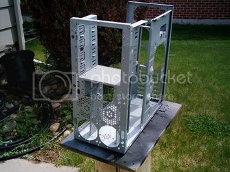
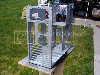
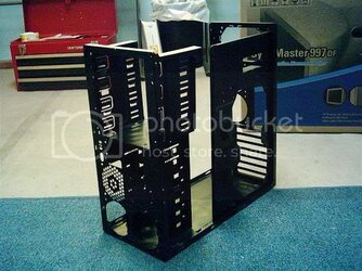
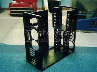
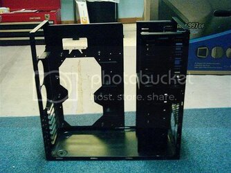
Thursday (5-5-05) I was going to paint the front of the bare case frame, so that it wouldn't look so ugly from the front panel window. I decided that since I had everything out of the case and it all disassembled I might as well just paint the entire thing....Heck, while I'm at it, clean up that back motherboard try cut!

Some pictures of the case, before painting:
unpainted5.jpg

unpainted2.jpg


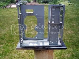
And here you can see how ugly the motherboard tray cut was. I had cut it right before I received the Zalman CNPS 7000-Cu, and I wanted easy access to the back of the motherboard if I ever wanted to change the cooler out, as well as the northbridge cooler. So it was basically done in about 30 minutes when it was first cut, including filing down the edges:
unpainted1.jpg

All I did to clean up the motherboard tray cut was straighten out the sides of the hole and make the corners a little sharper with a cutoff wheel on the dremel with the flex-shaft. It worked out pretty well. Sorry, forgot about pictures again. :(


So I got it all painted and clear coated, brought it in to dry and took some pictures. Here are the end results (I installed the top part of the case to make it a little more complete.
painted2.jpg

painted5.jpg
 
Last edited:
And a shot of the cleaned up mobo tray cut:
painted6.jpg


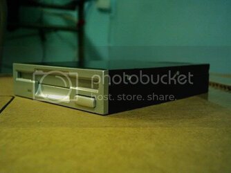
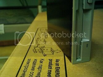
While waiting for the frame paint and clear coat to harden enough to install hardware, I painted the floppy drive casing to match the other drives. Lookin’ good I think.
Floppy_Drive_1.jpg

Floppy_Drive_2.jpg


While waiting for the clear coat to harden, I decided to put the side panels on, just to see how well it'd look through the side window. I had forgotten about the interior of the side panels and it looked really ugly with the steel side panel and then the black frame, so I painted those this morning, and clear coated them this evening, letting paint dry for 12 hours. I'll bring them in to harden some more tomorrow morning and take pictures.
 
Thanks itchy and ghettocomp. Funny you say that itchy, I'm a manager at McD's. :D

Time for another update. And as before, I'm late with it. :( However, I wasn't able to REALLY do anything (like wipe them down from paint dust and re-wax the exterior) until this afternoon. So I'd say they're pretty up to date.

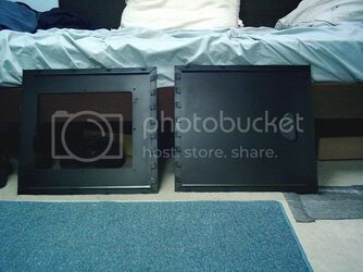
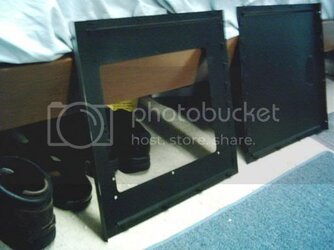
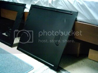
Here are the side panels with the black paint, and the matte clear coat on them:
Side_Panels.jpg

Right
Right_Panel1.jpg

Left
Left_Panel.jpg

Yes, that is a dent in the left side panel. I don't know how it got there, but it happened back when I painted this case. It wasn't as noticeable before it was painted as it is now, so even I was surprised when I saw it there.

I'd LOVE to repaint the exterior of this case again, same color but with a better job at clear coating it. As you can see, some of the edges have some paint missing from them. Unfortunately, some of the paint came off with the blue painter's masking tape I used. :(
 
Last edited:
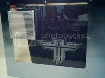
Some of you probably have never seen what was on the side panel window before I modded the case. Here you go....

Right_Panel_Logos.jpg

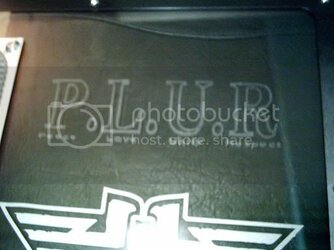
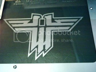
I did an etching which represented the music I listen to (Techno) and then I put a window appliqué of the Wolfenstein logo under it, which represents my favorite multiplayer game, as well as one of the only games we play at local mini-LANs (up to 14 people).

Right_Panel_PLUR.jpg

Right_Panel_Wolf.jpg

The 120mm fan grill to the left of the logos is from a duct I had done when I had an MSI board in there (before I upgraded to the ASUS), and the old Swiftech MCX370 heat sink had a 60mm fan on it. At the time, the duct lined up to the cooler on the CPU perfectly. After I upgraded the motherboard, the CPU socket wasn't in the same spot, and off by an inch. I figured instead of leaving an empty hole there, I'd just leave the aluminum 120mm fan filter over it, which has also helped give the CPU cooler fresh air, and lowered its temps 2-3°C.


As for the rest of this project....I'm still trying to figure out how and/or where to mount the temperature LCD. Where I had planned to put it just looks tacky now with the etching below it.

I still need to figure out how I'm going to "re-tap" the rear side panel screw holes, as well as what to do for a power switch. I wanted something wouldn't be REALLY obvious, but still not to hidden. The reset switch will still be going to the back, I need to get the time to figure out how I'm going to cut the hole in the back slot cover. I can't remember how I did it on my clear case mod...

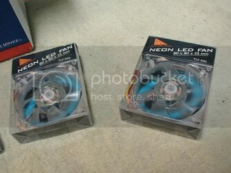
I did get the blue LED fans ordered from SVC. Four Cooler Master TLF-R82-BLU, Neon Quad LED Blue case fans. <catches breath>...Specs are as follows:

# Size: 80mm x 80mm x 25mm
# Rated Voltage: 12V
# Bearing Type: Rifle Bearing
# Input Current: 0.15A
# Rotation Speed: 2500RPM
# Acoustical Noise: 25 dB(A)
# Airflow: 32.11CFM
# Input Power: 1.80W
# Life Expectance (45-85% relative humidity):

* 50,000 hrs.
* 25,000 hrs. Continuous

I purchased them off SVC for $2.49 a piece, and it came out to a total of $16.82 with USPS Priority mail shipping. They should be here early next week, and I can start to put everything together again. :D
 
Last edited:
Celeron_Phreak said:
.....
Yes, that is a dent in the left side panel. I don't know how it got there, but it happened back when I painted this case. It wasn't as noticeable before it was painted as it is now, so even I was surprised when I saw it there.
.......:(

It is amazing how small imperfections like that will show up after getting freshly painted. You could always try to hammer that out, but painting will show it to look worse. Or, you could use a little bondo & some careful sanding and that dent will disappear.
 
I'm not going to fret over the dent. It's hidden by the motherboard, and I rarely remove the left side panels from my cases anyway.

Sjaak, what in the world is your avatar?? lol I'm not quite sure what you mean by a clear image of te RTCW logo. I found this applique on ebay for $1.99, I think, back when I was working on the Wolf ET - LAN PC mod. I don't seem them anymore, but I will try to find the sellers name andhis eStore if he's got one.
 
Send me a PM with your email and i can send you the large version of it. It's kinda hilarious.

I've been a great fan of RTCW myself, been looking for awhile for templates to spraypaint on my case, however, not anymore.
 
Hey, here's the user ID of the guy on eBay who sells the window appliques:

ShadowMajik

He doesn't just sell vinyl decals, he also sells case badges. Which reminds me. I need to pickup some AMD ones for a couple of my PCs....
 
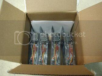
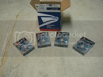
Well lookie here. We have something that's arrived early!
Fans1.jpg

What could they be???.....!!!!!!!
Fans2.jpg

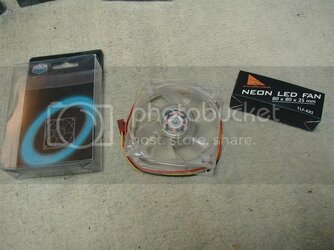
I wasn't expecting these until next week. SVC ships faster than I thought! Looks like I have another online store to add to my favorites list! :D
Fans3.jpg

Fans5.jpg


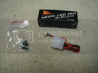
The little box that comes packaged above the fan contains a 3-pin to 4-pin molex adapter cable and the black annodized steel fan screws. To say the least, I was excited to see black fan screws come with a clear blue LED fan...Me painting the interior of the case black and all.
Fans6.jpg


So.....Tonight I'm going to be modding the power switch into the center of that 3.5" bay cover that I've been modding, and then I'm going to install these fans. We'll see what I've got in store for you later tonight. =D
 
These fans are going to be perfect. No louder than the old iCute, Panaflo and Nidec fans I was using in the case before (which all had the same or near the same CFM rating).

On to the update!

So I finally decided how to go about modding a reset switch to one of the rear slot covers. And it's actually very simple! I started out with the switch. I had an idea of how to do the slot cover in mind, so I decided to get the hard part over with.

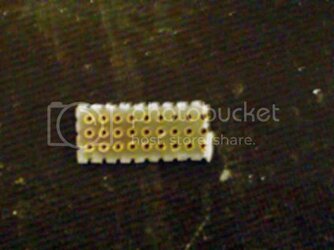
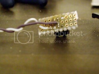
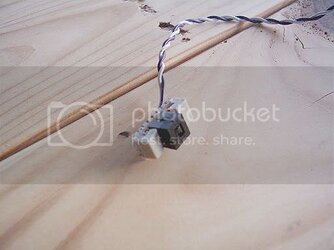
I started out with just these...a small section of printed circuit board, each hole is individual, not connected to each other. My dad brought some nice sized 7"x12" sheets of this stuff home back when he worked for HP 10 years ago (we rarely use this stuff). I removed the shrink tube from the leads of the reset switch as well as the original wires that led to the motherboard so I could mount the switch onto the PCB.
PCB.jpg

switch.jpg

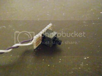
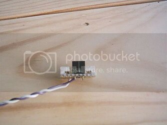
Then I soldered the switch to the board, added a dab of solder to one of the holes next to the lead, and soldered the motherboard wires onto the PCB. Here's what we have now:
siwtch2.jpg

switch1.jpg

Looks pretty nice I think. To bad it's going to be hidden, for the most part. You may be wondering why I left so much of the circuit board hanging out the sides....I hot glued two small chunks of plastic (cut off from and old plastic 3.5" bay cover) to the sides, so the switch wouldn't jut to far out the back of the slot cover. If you're still confused, you'll see what I mean in the pictures of the finished product.
switch3.jpg

switch4.jpg
 
Last edited:
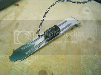
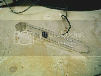
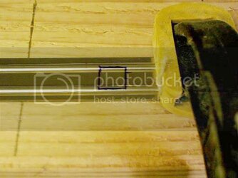
For the slot cover, I measured the switch size, then drew it onto the cover with a blue sharpie, something that I could see clearly.
back_plate1.jpg

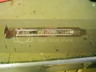
Using a 5/16" drill bit, I drilled a hole in the center of this blue square to start me off. Then using grinding stones and some very small files my dad happened to have, I made the round hole into a square one, without any sharp edges. Not the greatest, but it'll do.
back_plate2.jpg

Using hot glue once again, I put the switch through the hole with glue on the ears of the circuit board.

finished2.jpg

finished4.jpg

finished1.jpg

Now you can see why I put the two chunks of plastic there! If I hadn't, the switch would be hanging out a good deal, and might get in the way of connecting things in the future.

I have since added a small sticker on the rear panel which says "RESET" on it. Which you will see later tonight...If I don't forget about the update. o_O
 
Last edited:
Back