• Welcome to Overclockers Forums! Join us to reply in threads, receive reduced ads, and to customize your site experience!

VESA Wall Mount Project

Overclockers is supported by our readers. When you click a link to make a purchase, we may earn a commission. Learn More.
That’s it exactly

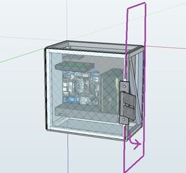
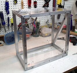
The TV bracket is attached to the frame with only 2 vertical points. So the weight of the TV is transmitted to the wall mostly thru this vertical plane.


Crossbar%2Bexplanation.jpg


So with gravity downwards, the weight of the TV is going to torque on the frame in the direction of the curved arrow. The crossbar counteracts the weight of the TV, keeping this panel square.

Now if you jerk the mounted TV around (in other planes)--which is not something I would expect to happen often--then you WILL add forces out of this plane, causing the other sides of the case to twist, so they definitely need to be strong.

So, how to keep the frame strong--rigid and square, was the reason I took so long to decide how to connect my framing elements together. The answer to which I will provide in a few short threads….
 
Last edited by a moderator:
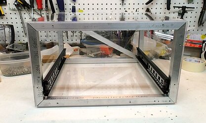
Frame Construction, First trial of slider action


While I mulled over how I wanted to finalize my joints, I decided to continue with the frame construction.

The next step was to mount my drawer slides.

Sliders%2Bfirst%2Binstall1.jpg


Sliders%2Bfirst%2Binstall2.jpg


And actually see how my motherboard tray action would work within the frame:

Sliders%2Bfirst%2Binstall4.jpg


Sliders%2Bfirst%2Binstall3.jpg


Quite well actually!


Here is a video with my first testing of the Tray and Frame action!


The project really turned the corner here. Having never built something quite like this, you’re never really sure it is going to work out, even after trying to plan and account for as much as you can. But I felt like this test really put the proof in the pudding. The rest of this project is details and execution.
 
Frame Assembly

Speaking of details, I finally decided how I was going to assemble the frame.

I was not going to assemble the frame.

After stopping in my nearby neighbor/local metal fabrication shop (Thomas Welding), I decided to have the frame professionally welded. No messing around, nothing would be more solid than making the frame one solid piece of metal. TIG welding aluminum is not something I felt I could learn easily for this project, so I subcontracted out.


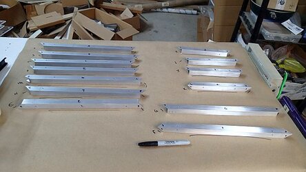
To prep my frame to head off to the welder’s, I labeled every piece and every junction.

Prep%2Bfor%2Bwelding2.jpg


And broken down:

Prep%2Bfor%2Bwelding1.jpg


Then it was off to the welder’s, just a few minute’s drive from my place:

Thomas%2Bwelding1.jpg

Thomas manufacturing, Chico, CA.


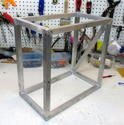
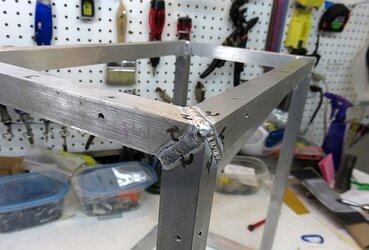
A week later it came back, looking awesome!

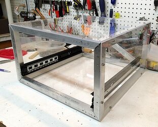
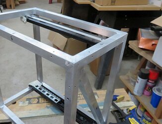
Frame%2Bwelded1.jpg

Most importantly, 100% solid. I could stand and jump on this frame all day long.


Frame%2Bwelded2.jpg

Solid bead of weld.
 
Frame finishing


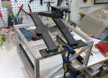
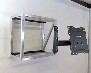
Took a moment to attach the TV mount arm to my frame. Pretty simple--I’m using 10-24 machine bolts with washers and nuts.

Wallmount%2Bbracket%2Bfirst%2Bfitting.jpg


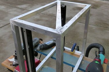
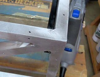
The next step was to grind down and pretty up the welds.

Welding%2Bgrinding%2Bwelds2.jpg

Having never really done this, I reached for all my tools on hand--random orbit sander with a lower grit, dremel, and multi tool.

Best process was to hit the bead of weld with my dremel with a sanding drum, but I went thru many many drums.

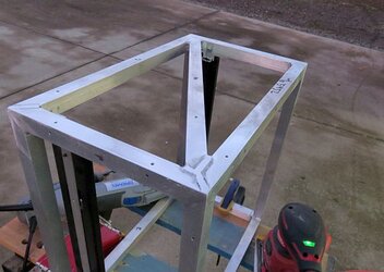
Then with a combo of the RO sander and multi-tool smoothed the weld flush.

Finished sanding to a smooth brushed finish with my hand block with 120 then 220 grit.


Welding%2Bgrinding%2Bwelds3.jpg


Welding%2Bgrinding%2Bwelds4.jpg


Welding%2Bgrinding%2Bwelds6.jpg


.
 
Last edited:
Wall Mount Bracket

The next step was to put together how I would mount this whole case to the wall.


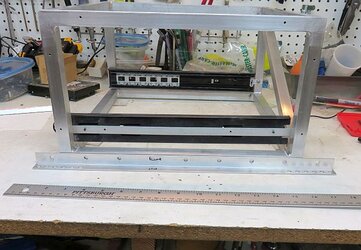
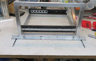
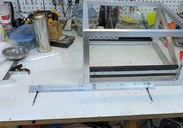
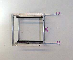
Each side of the case would mount to this long piece of angle aluminum:

Wallmount%2Bsystem1.jpg

The bracket is set to mount to wall with studs at 16” on center. Notice the multiple close holes on each end to accommodate up to 2” in variance.


Wallmount%2Bsystem2.jpg

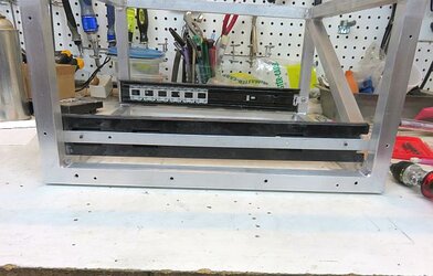
The bracket will mount to any 2 of these 4 holes in the base of the frame.


Wallmount%2Bsystem3.jpg

For example, the long screws represent where the bracket would mount to studs behind the wall. The 2 machine screws and washers mount the bracket to the frame.


Because of the multiple screw holes, you can mount the frame to the bracket off-center, to locate the TV at just about any point within the studs:

Wallmount%2Bsystem4.jpg
 
Very nice. I like the compound corners and how the welds turned out. Very nice indeed.
 
Testing the Wall Mount System


I’ve got my brackets built, so it was time to actually test wall mounting my case.


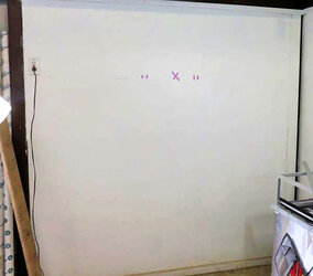
I chose the random X as where I wanted my TV to go. I then located my studs:


Testing%2BWall%2Bmount1.jpg


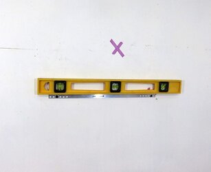
Next I mounted the lower bracket into the studs, making sure to keep it level:


Testing%2Bwall%2Bmount2.jpg


Followed by the top bracket and the case itself:


Testing%2Bwall%2Bmount3.jpg

Notice the “X” is right behind where the TV will sit.


This mounting quite strong--enough that I could actually hang from the bars of the case.


Next I bolted on the TV mount bracket:


Testing%2Bwall%2Bmount4.jpg


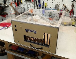
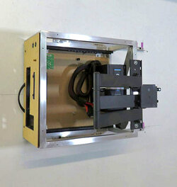
Final step was to slide the motherboard tray into place:


Testing%2Bwall%2Bmount6.jpg


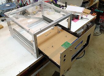
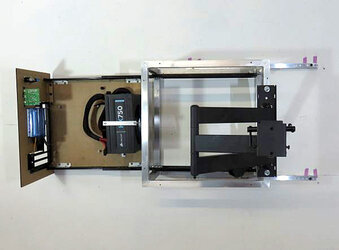
And when you would need to, you can pull the entire system out from the from on the sliders, giving you access to all the components:


Testing%2Bwall%2Bmount5.jpg
 
I love it Navig. This is the kind of ingenuity we expect from you here. Well done sir. I'm loving this build.
 
This is a nail biter for me. I'm looking forward to it but I'm worried about the forces transmitted through each member.

While you did say that the mount was strong enough for you to hang from, the real question is: can I hang from it? Scratch that, there is nothing that strong. Carry on. :)
 
The weakest link in the whole setup are the brackets that mount the case to the wall. They are made of only 1/16" thick aluminum, which is plenty strong enough for its purpose. But I suspect if you took a pry bar to the whole thing, you would get them to bend and buckle, far easier than actually do any sort of damage to the case frame as it is stabilized in 3 dimensions. I could easily beef up the bracket to 1/8", but 1/16" is plenty strong to hold up a case and TV.


Completing the motherboard tray and components


At this point of this build, my Dad requested a new PC, so most of the components previously pictured went into his system.

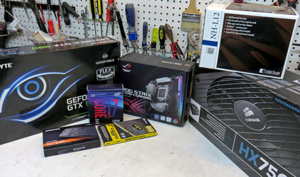
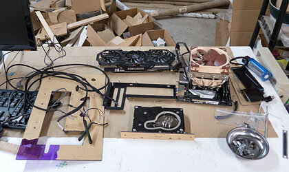
So it was time to go shopping, and here is what I ended up with:


Final%2Bcomponents.jpg

From before: Gigabyte GTX 980, Corsair HX750, and the Noctua NH L12.
New parts: i7 8700k, Asus ROG Strix mobo, 2x16gb Corsair RAM, and a Samsung 960 EVO M.2 drive.


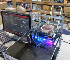
Threw these components on my test bench to make sure everything was working:

Final%2Bcomponents%2Bon%2Btestbench.jpg


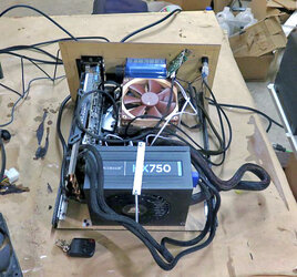
Next I made sure everything would fit on the actual motherboard tray:

Final%2Bcomponents%2Bmessy%2Bcables.jpg

This step is actually really important when working with custom cases and Mini and Micro ATX form factors because you just never know when you will run into something not fitting right.

Also, notice all the crazy wiring! The use of a wireless remote adds a lot of wires--one for internal power, and then doubles all your cables for power-on and reset. And I still haven’t added the second hard drive. Lots of cabling, not much space for maneuvering. Going to have to work on this.
 
Completing the motherboard tray and components, continued


I turned my focus of completing out the motherboard tray and all its components.


Minor housekeeping project: needed a power supply pass thru hole for the power supply cables:

PSU%2Bcable%2Bpassthru.jpg


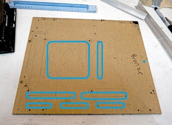
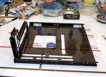
Next I worked on my cutouts for the motherboard tray:

Here was how I planned it.

Mobo%2Btray%2Bcutout%2Bplanning1.jpg

You’ve got the large cutout behind the cpu for access to mounting hardware. Next to it was a cutout to allow for air intake across the motherboard. The grill set at the bottom is for exhaust out the sides of the graphics card.


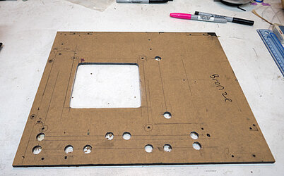
Here was the technique I used to make the cutouts. I used a unibit to cut out all the rounded ends.

Mobo%2Btray%2Bcutting%2Bpassthrus.jpg


Then connected the straight sides with either my plunge cut saw or my scrollsaw.

Mobo%2Btray%2Bcutting%2Bpassthrus2.jpg


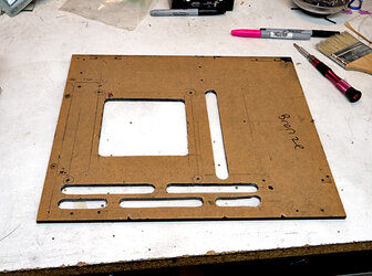
Then finished everything with a good round of sanding--with a dremel and by hand.

Mobo%2Btray%2Bpassthrus2.jpg

I will note that if you look at the last passthru at the bottom right, I made a mistake. During the stage where I was making the end holes, the drill bit must have wandered a bit, causing it to not be in alignment. I fixed it as best as I could with sanding and shaving, but it is far from perfect. This would later cause me to develop other techniques later on as I will have to do many more of these grill style air channels.

 
Completing the motherboard tray and components, concluded


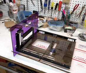
I started assembling all my components for the motherboard tray.

Tray%2BAssembly%2Bcomponents.jpg


Tray%2BAssembly%2Btray1.jpg

Mounting hardware for the tray including sliders and the PCI bracket.


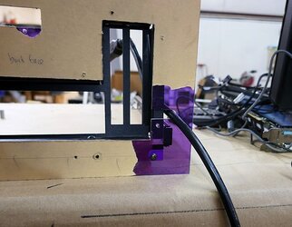
Added the vertical panel for I/O side.

Tray%2BAssembly%2Bpurple%2Bpanel.jpg


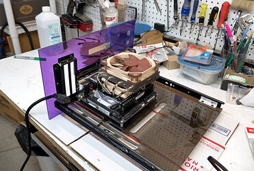
Next mounted the motherboard with the cpu and cooler:
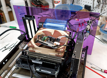
Tray%2BAssembly%2Bmobo1.jpg


Next I delved into all the wiring. Particularly for the remote system.

Tray%2BAssembly%2Bstart%2Bwiring.jpg


Add the power supply, which is a whole lot more cables:
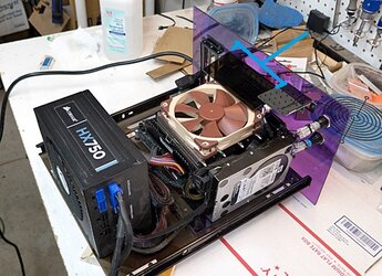
Tray%2BAssembly%2Bmobo2.jpg

Also note the blue bracket. I’ve attached a simple panel here on top of the exhaust blower. This is to force the exhaust to pull air from below the fins of the heatsink creating a push-pull air flow across the heatsink.


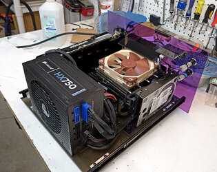
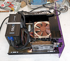
Finally, added the video card and this is a complete PC on a tray!

Tray%2BAssembly%2Bcompleted1.jpg


Tray%2BAssembly%2Bcompleted2.jpg

Here’s a little glimpse into all my cable management. My style of modding--I typically don’t do things like complete custom length and modded psu cabling. I like to keep my components fairly stock and warranty-intact. But you do then have to learn how to manage cabling. My trick is a lot of zip ties. I have also mounted a plastic hook to the backside of the PSU as a tether point to hold the cabling together.

A lot of other cables are tucked right next to each side of the heatpipes of the cpu heatsink. And quite a bit of cabling is hidden under the motherboard.


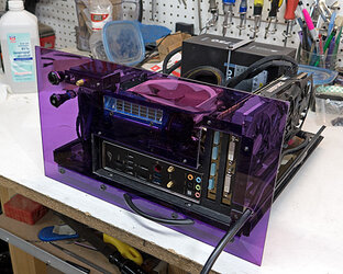
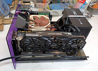
Tray%2BAssembly%2Bcompleted3.jpg


Tray%2BAssembly%2Bcompleted4.jpg
 
Just...wow. That is really impressive. The (lack of) space management and the quality of the fabbed parts is nothing short of exceptional. You really outdid yourself with this one, and I've followed several of your previous efforts so I know how high the bar is set. Congratulations are in order. :thup:
 
Thanks!


Paneling the frame


Next I cut rectangular panels that will clad the frame. Altho there are 6 sides to the frame, I only need 4 panels:, the motherboard PCI panel covers one side (which is already attached to the motherboard tray as above), and one side will be up against the wall so doesn't need a panel.

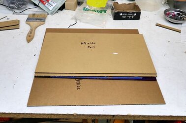
Panels%2Bcutting%2Bpanels.jpg


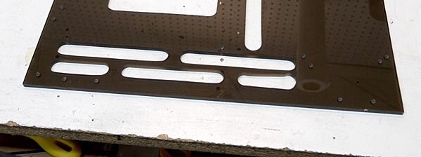
To create airflow, I planned making ventilation slots like I did for my motherboard tray:

Panel%2Bventilation%2Bslots.jpg


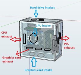
Here is a diagram of my planned airflow:

Airflow.jpg
 
Beautiful work sir! Been seeing it from you for the last 10+ years :)
 
Thanks again!


Paneling the Frame, Continued


I ran into some problems creating the slotted cutouts for my motherboard tray. So I wanted to try a different method--one that was more accurate and less accident prone.


So my plan was to use my router guided by prefabricated jigs.

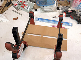
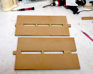
First I created my jigs:

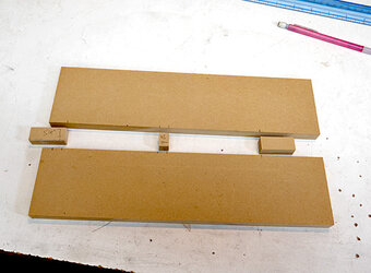
Panel%2Bjig%2Bconstruction1.jpg

Just some pieces of scrap mdf I had around the shop.


Glue and clamp:

Panel%2Bjig%2Bconstruction2.jpg


Panel%2Bjig%2Bconstruction3.jpg

2 different jigs--one for rows that will have 3 cutouts and one for 2 cutouts.
 
Paneling the Frame, Continued


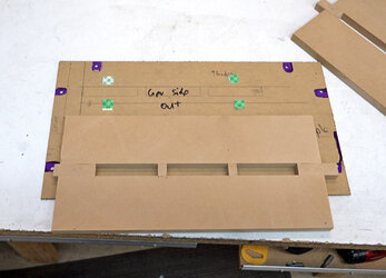
This is how the jigs work:

First, I attached a jig to my target plastic panel. I simply used multiple spots of double stick mounting tape. Obviously I made sure everything was aligned precisely and secured strongly.

Panel%2Bjig%2Buse1.jpg


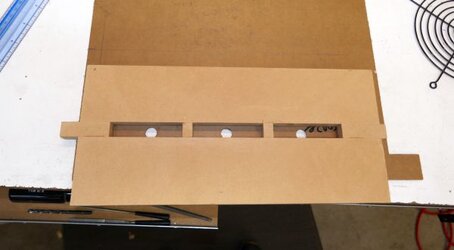
Once securely attached, I drilled in some pilot holes.

Panel%2Bjig%2Bconstruction4.jpg


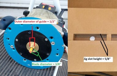
Next I busted out my router. The router has a jig guide installed--notice the brass bushing surrounding the router bit. This guide pushes up against the inside of the jig causing the bit to carve out a shape in reference to the jig.

There is a little bit of math involved. My ultimate goal was to have my cutouts ½” in width. I am using a ⅜” router bit, and the outer diameter of the guide bushing is ½”. That means that the outside of the bushing is ⅛” larger than the diameter of the router bit. So for a ⅜” bit to carve out a ½” hole, the jig slot must be ½” plus ⅛”, or ⅝” of a inch.

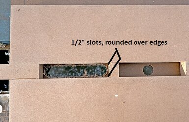
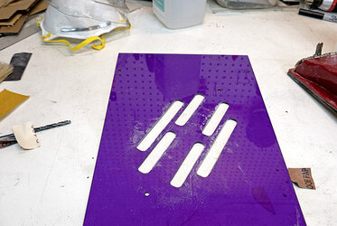
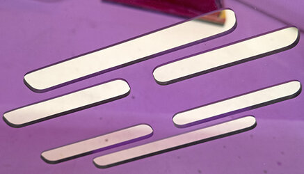
The end result are slots with ½” wide with corners rounded over to a radius of 3/16”.


Panel%2Bjig%2Bconstruction6.jpg


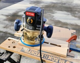
So with everything in place, I set the router with the guide engaged in the jig, drop router bit into the pilot hole, turn the router on, and slowly move the router bit along the inside edges of the jig:

Panel%2Bjig%2Bconstruction%2Brouter.jpg


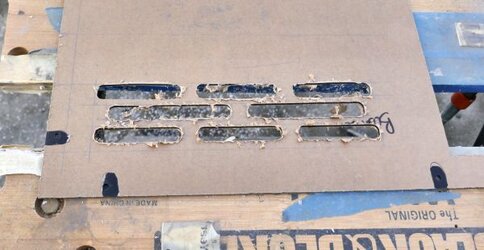
And here was the resultant cut:

Panel%2Bjig%2Baction%2Bcut.jpg


Repeat the same process, reposition jig, etc:

Panel%2Bjig%2Bconstruction%2Bslots%2Bdone.jpg
 
Paneling the Frame, Panels Completed


Next step was a lot of sanding:

Rough sanded edges:

Panel%2Bsanding.jpg

Outside edges I used a multi tool with 120grit, followed by hand sanding at 220 grit.

Inside curved edges were a pain! I mostly fingered sanded with 120 and 220 grit, then for the rounded corners I held small pieces of sandpaper to a drill bit.


End result was pretty nice:

Panel%2Bsanding2.jpg


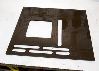
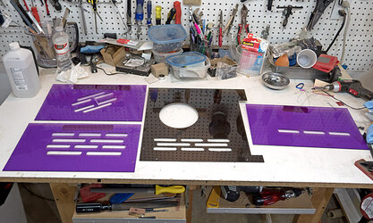
And here were my finished panels:

Panels%2Bcomplete.jpg
 
Back