• Welcome to Overclockers Forums! Join us to reply in threads, receive reduced ads, and to customize your site experience!

Exoframe 3D

Overclockers is supported by our readers. When you click a link to make a purchase, we may earn a commission. Learn More.

Navig

Senior Case Master
Joined
Dec 7, 2003
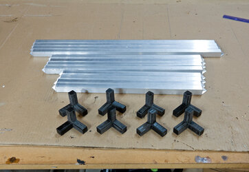
Corner bracket start small.jpg

Exoframe 3D
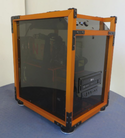
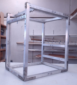
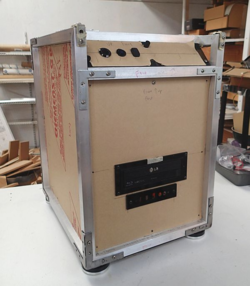
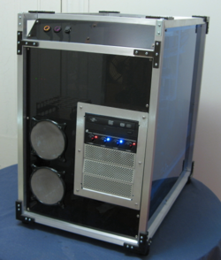
This is the build log for my latest scratch built mod. It’s been a little while since my last post (Vertical Benching Station), due to life, and some health issues. Exoframe 3D is based on my previous concepts of an Exoframe--a chassis of square tube aluminum, with inset acrylic paneling.

The “3D” portion of the name may be a little confusing, as obviously the mod is 3 dimensional. “3D” refers to the incorporation of a new skill set to my modding:
a 3D printer!

Post magically merged:

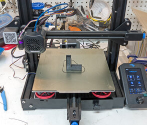
Let me introduce you to my 3D printer:
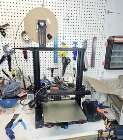
Ender 3v2.jpg

Bought off Amazon Prime Days, I picked up the Creality Ender 3 V2, the quintessential DIYer’s 3D printer. If you aren’t familiar with 3D printers, this is the general starter’s 3D printer for people who want to learn about 3D printing and be able to troubleshoot a printer. This is not the fully assembled bells and whistles ready to go out of the box printer.

So of course, here are my mods and upgrades:
Upgraded springs
Cable clips and filament holders
CR Touch auto bed-leveler
Flexible magnetic bed
Capricorn tubing
Filament sleeve mod

Generally, I've been using Inland black PLA.
 
Last edited:
Background and Planning

The Exoframe 3D is going to be my own new personal system, replacing my Vertical Benching Station. I (actually my wife) wanted something a little more contained. As it is going to be my own personal system, I would say the balance of the mod will be 80% function, 20% aesthetics.

As mentioned, it will be based on the concepts of my previous Exoframe projects.


The original Exoframe.

1681883326213.png


My most recent, the Exoframe mini.

1681883326254.png


The 2 basic principles guiding the aesthetics and design of this case::

1. Square tube aluminum frame, putting the FRAME in Exoframe

1681883326285.png


2. Inset plastic paneling, putting the EXO is Exoframe.

1681883326336.png
 
Layout Mockup

I like physical mockups to determine my layouts. I have these old extruded aluminum sets with which I can build temporary frames to give me a physical model to play with--exactly the same bars that comprise the frame of the Ender 3.


Mockup1 labeled.jpg


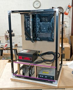
This is my general layout for the front side. I’ve got the motherboard vertical on a large panel that will be ¼” acrylic.

Then a level for the power supply.

Underneath another level for old school hard drives, and even some old school 5.25 bays. I still like having these slots.


This is my plan for the backside:

Mockup2 labeled.jpg

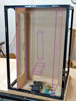
On the 2 sides will be 2 air chambers which will mount 2 4x120 radiators. Running up the middle will be my pump system and a reservoir.
 
Let’s get to creating!


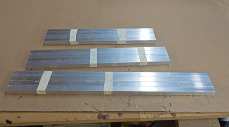
Starting with stock metal--Square tube aluminum, .75”, 1/16” wall thickness. Nice and light, easy to work with, plenty sturdy for PC case purposes.

Metal is cut.jpg


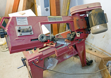
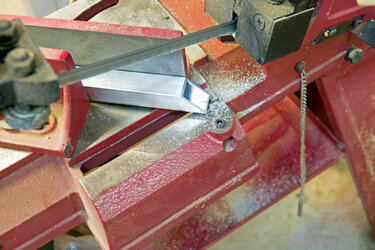
To join the corners, I am going with a double miter. I cut my aluminum with a cutting band saw:

Metal cutting bandsaw.jpg


Going for the second miter:

Cutting double miter.jpg


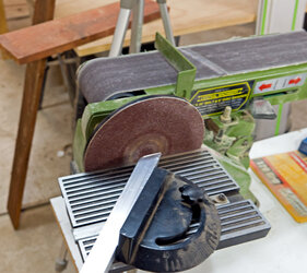
Sand and refine on a disc sander:

Sanding edge.jpg


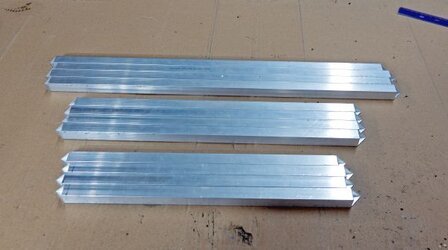
And here are the bars for the frame, all nice and pointy double mitered.

Metal mitered.jpg
 
Time to connect the square tubing


Now that I had cut all the frame posts, it was time to connect them!


Corner bracket examples.jpg

In the original Exoframe, I built my own external brackets from ¼ in acrylic (Left).
For the Exoframe 2 and Mini, I subcontracted a local steel laser cutting shop, and manufactured a steel bracket (Middle).
For the VESA Wallmount project, I hired a local company to TIG weld the corners (Right)


Time to put the 3D printer to work!

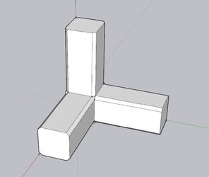
I designed this all-internal 3 way corner bracket (Sketchup):


Corner bracket sketchup.jpg


Each leg is about 2.5” in length, and each leg has a width and height of 15.64mm. The 15.64mm is the exact size to snugly fit inside my square tube aluminum, which is standard size of ¾” square, with an interior wall thickness of 1/16”.


Internal bracket printing.jpg
 
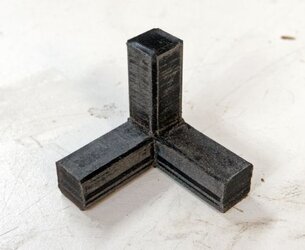
Off the printer and sanded to fit:

Bracket sanded.jpg


The fit of the bracket is very tight/slightly too large. After printing, I sand down each bracket to just fit into the individual joint, and labeled the bracket as the fit is so snug, each corner is specific.


You may have noticed that I put a small bevel on each of the edges of the legs of the bracket--this is something I learned from my first prototypes that had the simple squared off corners. When you go to sand a squared off corner, material gets pushed over the edge and accumulates on the adjacent face, creating a lip that gets caught on the square tube's inside edge. Anyways, by adding the bevel, the negative bevel space collects the extra material so that there is no lip proud of the surface.

I designed the 3D model with Sketchup Pro (as mentioned), and sliced it with the Creality Slicer with the following settings: 3mm wall thickness 20% gyroid infill, temp 220F. I used Hatchbox and Inland standard black PLA filament. Takes about 3.5 hours to print each bracket.


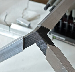
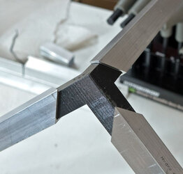
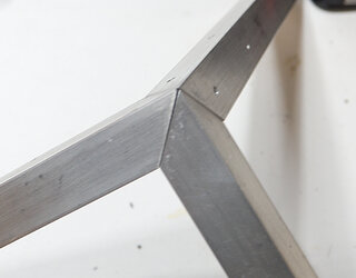
Once sanded, connecting the corners can be as simple as sliding the brackets into the mitered ends to form the 3 way corner:

Corner bracket start small.jpg


Mitered corner.jpg
Post magically merged:

And here are the structural elements for this frame:


Frame components.jpg
 
Last edited:
I know I'm late to this post but I really like what you've done here. Great idea to make the joints cleaner.
 
Back