• Welcome to Overclockers Forums! Join us to reply in threads, receive reduced ads, and to customize your site experience!

FX-8350 CPU/DIE Orientation + Raystorm Mod

Overclockers is supported by our readers. When you click a link to make a purchase, we may earn a commission. Learn More.

mongoled

Member
Joined
Jul 9, 2002
Location
Sotira, Cyprus
Hi!

Have done a little bit of researching for my own use so may as well put it here so others, if they wish to do so, can use.

Basically what it came down to was that with a vast range of waterblocks on the market each performing differently on different CPU's, I wanted to know what I could do to make sure my Raystorm waterblock was working as efficiently as possible for my FX-8350 CPU.

So below are my findings.

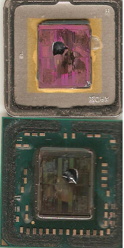
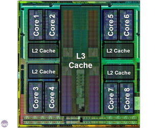
Firstly, I used two images from the web to get an approximation of a few things (images below).

fx-8350-delided.jpg
piledriver-die.jpg

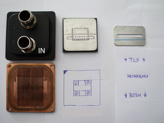
The next image shows my findings which I will discuss.
fx-8350-orientation.jpg

OK, firstly, I wanted to know where the cores where in relation to the inlet of my Raystorm block.

As can be seen in the images, the inlet lays right in the middle of the CPU (which we can see is directly above the L3 cache).

So what I will be doing is to create a new inlet plate so that the water will first 'hit' cores 5/6/7 and 8 first, then move other the L3 cache and then finally over the other cores.

When pushing for maximum prime performance it is almost always core 5 and 8 that I have issues with so will find out if my mod will make any sort of difference.

This will be the first step, as alot of us know these FX CPU's are really picky once they go over 62C package temperature.

So anything I can do to keep lower than this can only be good!

:)

Anyhow, will post back when I have some results (wont be for a good week while I wait for a replacement CF5-Z to arrive).
 
Last edited:
You have my attention on this one.

Very interesting concept to force cool specific parts of the CPU. Overall though, this may not cool down the CPU as much as you are hoping for. Here is why:

In terms of temperature, the CPU could be divided into two parts: the package and the die. The temperature from the die is due mostly to the switching of all the tiny transistors. So thus higher frequency higher temperature. The temperature from the package deals more with the power, since most of the traces and pins are power connectors. So thus more volts, higher temperature.

If you decided to concentrate on one area, you could end up allowing the other to produce to much heat. Thus no optimization achieved. To optimally design this you need to do a bit of research. Figure out what affects the temperature more: frequency or voltage? Your best bet for doing this is to test how quickly a specific feature (frequency/voltage) achieves a specific temperature. The faster it is, the more likely it produces a higher amount of heat.
 
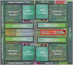
I agree with Dolk on this I know this is a bull dozer shot but the architecture is similar. IMO the IMC is one of the most sensitive parts of the die and one of the hottest. It affects your OC in a big way. It's located in the center of the die.
untitled.png
You can achieve a higher clock with a lower CPU_NB speed. You're correct in your thinking temp is king with these CPUs
 
im subbed, and your findings could shape future cooling if good!
Hi! Thanks for your kind thoughts, but i think that would be dreaming a little

:p

You have my attention on this one.

Very interesting concept to force cool specific parts of the CPU. Overall though, this may not cool down the CPU as much as you are hoping for. Here is why:

In terms of temperature, the CPU could be divided into two parts: the package and the die. The temperature from the die is due mostly to the switching of all the tiny transistors. So thus higher frequency higher temperature. The temperature from the package deals more with the power, since most of the traces and pins are power connectors. So thus more volts, higher temperature.

If you decided to concentrate on one area, you could end up allowing the other to produce to much heat. Thus no optimization achieved. To optimally design this you need to do a bit of research. Figure out what affects the temperature more: frequency or voltage? Your best bet for doing this is to test how quickly a specific feature (frequency/voltage) achieves a specific temperature. The faster it is, the more likely it produces a higher amount of heat.
Hi! All your points are entirely vald, all the things you have described above play a part in, as we know heat.

My experiment is just to see if by using a purposefully modified inlet we will see any sort of change in temperature AND a change in characteristic of the CPU when put under high load using prime95 blend test.

I doubt there will be a decrease in overall temperature, im hoping to see a difference onto which cores fail.

;)

I was sitting today trying to visualise what it would be like to be a water particle traveling in from the waterblocks IN tube, the first thing I see is a vertical wall, upon which i will hit and create turbulence before being forced upwards to wards the inlet.

Now if the vertical wall was instead a 45 degree slant then instead of 'smashing' into the wall and knocking into other incoming particles instead I would move upwards to wards the inlet!

But without the aid of a water particle simulator and building the waterblock in a 3D program such as 3dsmax, softimage etc all I can do is visualise and put what I see into practice.
I agree with Dolk on this I know this is a bull dozer shot but the architecture is similar. IMO the IMC is one of the most sensitive parts of the die and one of the hottest. It affects your OC in a big way. It's located in the center of the die.
View attachment 137605
You can achieve a higher clock with a lower CPU_NB speed. You're correct in your thinking temp is king with these CPUs
Yup, we are all in agreement

:)

Personally, the config in my sig does not abide with what you said regarding total clock speed and lower NB clock speeds.

The max I can bench Cinebench 11.5 and 15 is 5298mhz. Even decreasing NB clock speed along with other variables I have not been able to go over this speed.

Not saying that what you have said is incorrect, on the contrary I am in agreement :D . Just I havnt found a way to make it work with the setup in my sig and never will.

That board has gone and a new (i hope its new) will be coming to replace it the Z variant.

I will post up pictures tomorrow of my test inlet.

Hopefully the motherboard will be here some time next week and we can see some results

:p
 
I see that you have a setting of 1.55v + LLC at ultra which will probably put the Volts under load in the 1.57 range for 5.0 stable. Now you say it won't go higher, you mean stable at a higher clock. Just from what I have seen with my CPUs once you get to that point the V_Core needed for the nest 100MHz is a lot. SO at a guess That would put you in the 1.65v range and I doubt your cooling could handle that under ambient temps.
5.0 stable is nothing to sneeze at, that's a great clock to start with. What is your goal, benching??
 
Interesting.

I guess my fist impression would be that it wouldn't matter where the water went first, last, in between, or whatever because the water is making very little contact with the plate.

Physics states that no matter the orientation, in a perfectly isolated and insulated standing pool of water, an object that is warmer than the water will cool down and the surrounding water will heat up until it reaches equilibrium and then there would be no more heat transfer.

But of course a liquid rig isn't standing. For every 10mm^3 of warm water there is coming out, it will be replaced by another 10mm^3 of cool water coming in. Thus helping cool the system even more.

HOWEVER we forget the isolated part of the system, which is key. These are closed (read: Isolated) loop systems and eventually, just like the pool of standing water, the warm chip will reach equilibrium with the cool water in the system, unless if there are external forces applied. That's why we have rads (read: external forces) to help remove the heat out of the system, but they have a fixed amount of potential depending on the room's temperature.

tl;dr: When the water reaches equilibrium temperature it won't matter where you put the inlets. But I digress...

EDIT: The only thing that changes the behavior of a chip is electricity, heat, and the purity of its manufacturing. The chip itself is isolated for the water(if not, you might want to check that) so it wouldn't help change the behavior.

Did you blow that board already or did you not find a workable BIOS for the CHV-Z?
 
I see that you have a setting of 1.55v + LLC at ultra which will probably put the Volts under load in the 1.57 range for 5.0 stable. Now you say it won't go higher, you mean stable at a higher clock. Just from what I have seen with my CPUs once you get to that point the V_Core needed for the nest 100MHz is a lot. SO at a guess That would put you in the 1.65v range and I doubt your cooling could handle that under ambient temps.
5.0 stable is nothing to sneeze at, that's a great clock to start with. What is your goal, benching??
Hi

:)

again all valid points.

You are right on the ball regards the voltage underload with the LLC settings in my sig.

Also my CPU is exactly like what you have described above, to gain anything higher than 5000mhz 'stable' requires 'rediculous' amounts of voltage and as you have said, the extra heat output cant be handled by my rig.

Im actually trying to tweak that little bit more out of my setup so I can reach a 5350mhz overclock for benching cinebench 15, im very close to the next guy in the list (over at XS)

:D
Interesting.

I guess my fist impression would be that it wouldn't matter where the water went first, last, in between, or whatever because the water is making very little contact with the plate.

Physics states that no matter the orientation, in a perfectly isolated and insulated standing pool of water, an object that is warmer than the water will cool down and the surrounding water will heat up until it reaches equilibrium and then there would be no more heat transfer.

But of course a liquid rig isn't standing. For every 10mm^3 of warm water there is coming out, it will be replaced by another 10mm^3 of cool water coming in. Thus helping cool the system even more.

HOWEVER we forget the isolated part of the system, which is key. These are closed (read: Isolated) loop systems and eventually, just like the pool of standing water, the warm chip will reach equilibrium with the cool water in the system, unless if there are external forces applied. That's why we have rads (read: external forces) to help remove the heat out of the system, but they have a fixed amount of potential depending on the room's temperature.

tl;dr: When the water reaches equilibrium temperature it won't matter where you put the inlets. But I digress...

EDIT: The only thing that changes the behavior of a chip is electricity, heat, and the purity of its manufacturing. The chip itself is isolated for the water(if not, you might want to check that) so it wouldn't help change the behavior.

Did you blow that board already or did you not find a workable BIOS for the CHV-Z?
Hi

:)

nicely wrote, all valid, ofcourse we use technology :) and science to assist us ofcourse I dont have the tools ready to run my own simulations.

:p

I believe my mod will change the manner the water moves around the block, now if we can see tangible evidence of this assumed change we will find out.

No I think he is replacing the earlier non-Z CHV with the CHV-z.
RGone...
Hi!

:D

You got it spot on!

He had on another thread asking what BIOS version everybody was running on that board which gave me the vibe he already had the board.
Yup, thats correct, just preping myself so when it comes I already know the ins and outs of various BIOS's and peeps observations

:)
 
Hi

:)


Im actually trying to tweak that little bit more out of my setup so I can reach a 5350mhz overclock for benching cinebench 15, im very close to the next guy in the list (over at XS)


:)

Ya I posted my 9370 in that thread, haven't been over there for a while. I hit 887 with my 8350 in that bench. That one is a lot harder on the CPU than R11.5.
 
Ya I posted my 9370 in that thread, haven't been over there for a while. I hit 887 with my 8350 in that bench. That one is a lot harder on the CPU than R11.5.
Ha! Well for sure Im not going to catch you, LOL

but the others maybe just maybe.

I say this because all my benching is done from a closed case system without any 'extreme' methods of cooling.

Thats the restriction I have put in place, i.e. any scores I put out are from my regular desktop.

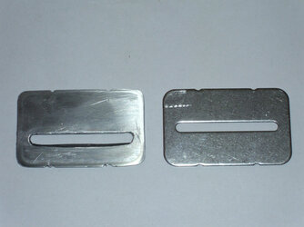
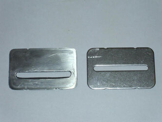
Anyhow, here is a pic of the inlet that my brother help me make.

inlet.jpg

Should be OK for testing, if there are positive results then will make a copper inlet.

The inlet is aluminium and I know metals shouldnt be mixed, but it wont be used long, just for this test.

Anyhow, my brother wants to do an even more extreme mod, but it wont be a good idea as I remember from my previous readings into direct die water cooling.

So I found the old threads and re-read up on peeps results and it does not look like it is worth revisiting, main reason being is that water eventually finds its way through the pcb substrate and ends up killing the CPU.

I dont think the materials they use in the pcb have changed that much over the years.

Will be looking into grinding down the ihs instead on a metal grinding machine, am in the process of buying a broken AM3 motherboard and cheap AM3 CPU so that I can use the socket as a holder for the CPU and the cheap CPU as a test.

I dont know the thickness of the IHS, would it be safe to assume that all the IHS that AMD use are of the same thickness ?
 
Last edited:
Just a quick question here, are you trying for a laminer flow here and I would consider the size of the slot carefully since pressure could come into play as well.
 
Anyhow, here is a pic of the inlet that my brother help me make.

y9vw5vk7hilku6c4g.jpg

Should be OK for testing, if there are positive results then will make a copper inlet.

?

Could you upload the images directly to the site?? Your links won't work for some peole. Just go to advanced post menu and use the paperclip.
 
Just a quick question here, are you trying for a laminer flow here and I would consider the size of the slot carefully since pressure could come into play as well.
Nope not laminer flow.

Keeping (well attempting to) the size of the slot exactly the same, just its positioning is being changed.
 
Could you upload the images directly to the site?? Your links won't work for some peole. Just go to advanced post menu and use the paperclip.
Oh sorry, I was not aware of some people having issues with the images.

Will do so for future images
 
Back