• Welcome to Overclockers Forums! Join us to reply in threads, receive reduced ads, and to customize your site experience!

Made my own DDC acrylic top- How & Pics

Overclockers is supported by our readers. When you click a link to make a purchase, we may earn a commission. Learn More.
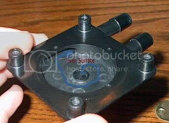
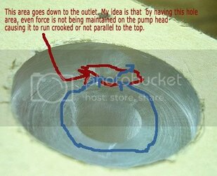
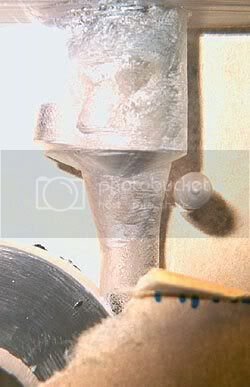
I've been sitting here studying the original top and my top. There is one difference between the two that I didn't think would matter, but apparently it does. The difference is that I have water going out through a hole that uses some of the interior curve of the chamber over the pump head. The original top has all of the water going out of the side and only a smooth surface over the area of the pump head. By not having an even surface over the entire chamber over the pump head, this is causing the pump head to turn at an angle and rub the top interior. It must be the smooth, consistent surface totally over the pump head in order for even force to keep the pump head running parallel to the top.

I have ideas of how to mirror exactly the original design and still incorporate the 1/2" outlet. If I have time tomorrow, I am going to give this another crack.
 
Hey, I've got a theory for you to test, Voigts. Does the impeller lean toward where the outlet joins the impeller chamber? If so, perhaps the opening from the chamber to the outlet, is too wide. It could be that in the original design, the water and walls help center the impeller, and in yours, the outlet side is too "soft". If it leans a different way every time, then maybe your whole chamber is too big, or perhaps a bit too deep.

Edit: LOL, you're ahead me. :) Good luck.
 
Otter said:
Hey, I've got a theory for you to test, Voigts. Does the impeller lean toward where the outlet joins the impeller chamber? If so, perhaps the opening from the chamber to the outlet, is too wide. It could be that in the original design, the water and walls help center the impeller, and in yours, the outlet side is too "soft". If it leans a different way every time, then maybe your whole chamber is too big, or perhaps a bit too deep.

Edit: LOL, you're ahead me. :) Good luck.

It leans towards the outlet which is what is telling me that is the problem.

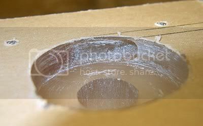
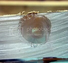
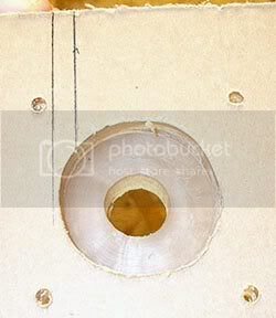
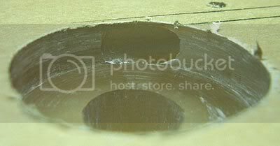
Here are a couple of pics to explain what I am thinking is my problem.

problemPic2.jpg

problemPic1.jpg
 
Otter said:
Any idea how long Clocker2's top has been in service and if he runs the pump 24/7?
My pump has not run at all as yet...either in stock form or with the Radical head.
I was waiting on my replacement Stasis Thermal Neptune block to arrive before I made the switch from 1/2" to 3/8" (D5 to MCP rev.2).
Should happen this weekend.
 
voigts said:
It leans towards the outlet which is what is telling me that is the problem.

Here are a couple of pics to explain what I am thinking is my problem.
Yeah, I see what you mean.

It's hard to tell in that pic, but it looks like you've got a channel leading almost all the way from the inlet to the outlet. Robotech reported slightly lower head after the mod and speculated it might be from increased leakage. This makes sense because with his mod you remove that little lip that extends down into (or almost into) the eye of the impeller, and that allows a wider path from the outlet side back to the inlet. It seems to me yours might have even more of this problem as it is now.
 
I noticed that the real pump top has the exit on the outside of the ring, and yours... isnt. Maybe that is the problem
 
Otter said:
Yeah, I see what you mean.

It's hard to tell in that pic, but it looks like you've got a channel leading almost all the way from the inlet to the outlet. Robotech reported slightly lower head after the mod and speculated it might be from increased leakage. This makes sense because with his mod you remove that little lip that extends down into (or almost into) the eye of the impeller, and that allows a wider path from the outlet side back to the inlet. It seems to me yours might have even more of this problem as it is now.

If I remember right, it was only a .2psi difference before and after which makes the mod well worth it. I hadn't thought of this issue but you are right. The way it currently is would be a problem. So many problems, so little time...

Maybe I'll get back to the drilling/sanding board tomorrow and see what I can do.
 
DickH said:
I noticed that the real pump top has the exit on the outside of the ring, and yours... isnt. Maybe that is the problem
Oh yeah, it's not really tangential is it. I didn't notice that before. That might not be the source of the problem with the impeller, but I think it will be a problem for performance.

Voigts, are you going to start over or try to fix what you've got? Maybe you can fill in with epoxy or epoxy putty for a temporary fix, and then make a new top once you figure out how to do it right.
 
Otter said:
Oh yeah, it's not really tangential is it. I didn't notice that before. That might not be the source of the problem with the impeller, but I think it will be a problem for performance.

Voigts, are you going to start over or try to fix what you've got? Maybe you can fill in with epoxy or epoxy putty for a temporary fix, and then make a new top once you figure out how to do it right.

I'm going to start over as I have some ideas as to how to remedy this. It doesn't really take much time to make a block. The longest part is really just cutting the threads.
 
Revision 3

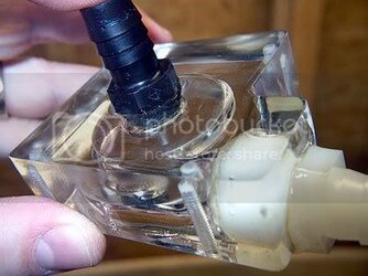
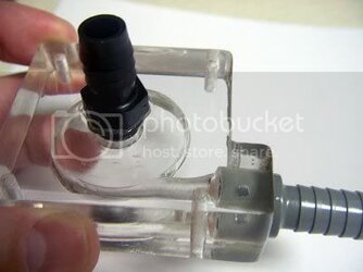
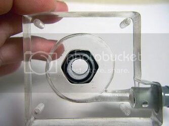
Well, I went at it again for a few hours this morning working on revision 3. The person I was going to buy a radiical from fell through, so I am more motivated to try again, not to mention the fact that I don't like to not make something work. Clocker2 helped me here in that he has a radiical block and let me know that the outlet path on it is 1/4", which is the size of the original top, and the outlet does not intrude into the pump head recess area. With this info in mind, I set out this time to copy the top as exactly as possible making sure the outlet goes from the side and does not intrude on the chamber area as with the first two attempts.

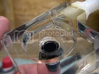
This time instead of just measuring the top area I actually took a piece of paper and exaclty traced the top to make a template. After drilling my 1 1/2" diameter hole, reaming out the spiral, and drilling the mounting holes, I copied the 1/4" outlet path that the original top has.

IM000004.jpg

IM000006.jpg

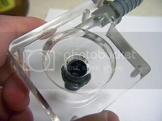
I then pulled out my trusty Nokita rotary tool and reamed out the side channel just like the original top.

IM000008.jpg

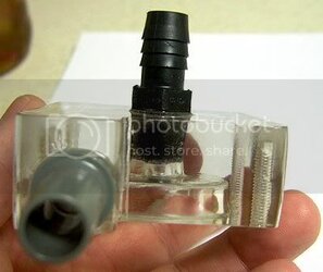
In order to drill the hole for the outlet barb, I had to drill it very close to the edge because of how the 1/4" outlet path comes out close to the edge. So close that trying to tap threads was not going to work. I decided to just go ahead and epoxy the barb into the outlet hole. I kind of wish I would have thought of that first as I would have made the outlet hole smaller, but it should still work. I also reamed out where the 1/4" outlet path meets the barb area so that there is an even transition. This also put this VERY close to the mounting hole on that side.

IM000012.jpg

IM000010.jpg
 
Last edited:
Ok, final pics. The epoxy has to cure so its got to sit until tomorrow afternoon. I used the rotary tool to sand off the threads from the barbs in order to get them into the holes.

IM000013.jpg

IM000017.jpg


IM000015.jpg

The edge was so thin that when flame polishing it recessed a bit, but with epoxying the barb, it won't matter.

IM000016.jpg

I guess I'll see tomorrow night how this does. Being that it is as close to the original top as I can get, I think this will be a go.
 
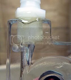
Well, being a perfectionist is a pain at times. Although I think revision 3 will work fine, I still wasn't quite happy with the way the outlet looked. So I went back tonight and made a revision 4. This time I think it came out about as close to perfect as I am going to get. Epoxying the barbs really helped the whole process as it made for a much easier outlet hole design since I only need a 1/2" hole to epoxy into and the edge can be thin, whereas if tapping out, the edge can't be thin and it takes a 9/16" hole. I just had to drill a 1/2" hole for the outlet and then drill within that hole a 1/4" hole for the outlet path. It also made it a lot easier to put a little space between the outlet path and the mounting hole. Anyway, here are the pics. I look forward tomorrow night at firing this up once the epoxy cures.

IM000007.jpg

IM000009.jpg

IM000010.jpg

IM000008.jpg

IM000011.jpg
 
Last edited:
Just in case your "inner perfectionist" (or "inner masochist", as the case may be)
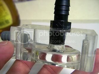
decides to try for rev.#5, here is a shot that shows how Radiical got around the output barb threading problem*...
radiical1.jpg

As you can (kinda) see, the barb is centered in the sidewall and the small channel angles down to the impellor cavity.
It does appear possible to drill this hole, given a bit of sufficient length, but I still think these are actually cast with only finish machining done to clean up the channels and edges.


*Sorry it took so long to post up this pic.
I watched helplessly from work as you produced not just one but two new revisions before I got home and then I thought you were done...but nooooo, had to go and make yet another, didn't you?

Now I suppose you'll be forced to start yet again....
 
I am sure that they cast the pieces. That would be the only efficient way to make them for sale and get them accurate. I wish I would have had some detailed pics of the radiical top before I started. It would have saved me a lot of work. I thought of doing the exact same thing with angling the outlet path, but then you run into the problem of how to have the outlet enter the chamber properly when drilling. It could be done if I drilled almost into the chamber area at the angle and then using a rotary tool from there, but it is easier to drill out a non-angled path like the original top instead. The angled path is not something that i am going to go back and make another to change. Epoxying the barbs in works just fine for me.

I just hope that when I can test my top tonight, it performs correctly.
 
Last edited:
i dont think they cast them. Usually when stuff is cast it is much cheaper than a machined part. If they are casted, they must make a lot of profit on those tops.


I call revision 3!!! j/k

rev 4 looks really good. hopefully it works.
 
nachosyumm said:
i dont think they cast them. Usually when stuff is cast it is much cheaper than a machined part. If they are casted, they must make a lot of profit on those tops.


I call revision 3!!! j/k

rev 4 looks really good. hopefully it works.

I will probably test both 3 & 4 later tonight or in the morning. I am willing to part with number 3 IF it tests out OK. IF I do, I'll let you know. ;)
 
Well, I did some flow testing. Mind you this is not exactly a scientific test procedure on my part, but what I am after is the difference using the top.

Rev4 works perfectly. This is the final revision that I got VERY close to the original top spec.

The rev3 top also works fine with one minor issue. When I cut it, I was a little off on the impeller chamber depth by almost 1/16" giving almost 1/8" clearance between the impeller and the top, whereas the original top only has 1/16" clearance (as does my rev4). This makes the impeller run a little out of parallel with the top and hence just a little louder with a little more vibration. That 1/16" clearance is obviously crucial to maintain the best pressure and hence alignment of the impellor.

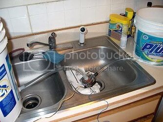
Here is a pic of what I did to flow test:

flowTesting.jpg

One bucket has a barb screwed into it going into the inlet of the pump in the sink going out to another bucket back on the countertop. I measured 2 gallons in the receiving bucket and marked it with a line. I then filled up the barbed bucket, and ran my stopwatch timing how long to fill 2 gallons.

As I mentioned above, with the stock top, it took 90 seconds which calculates into 80GPH/303LPH.

With either my rev3 or rev4 top, it took 51 seconds which calculates into 141GPH/534LPH.

This comes out to a 76% improvement in flow over the standard top. Like I said, this is not scientific, but it bears out that there is a very significant improvement over the standard top. I wish I had a way to test the pump PSI, but I am figuring based on Robotech's results doing the flow mod at systemcooling.com that there isn't much of a difference.

Yeah--- it works and lives! :clap:
And not too bad on cost. I spent $20 on 7 acrylic pieces (still have 3 left), and about $5 on barbs. This took a good bit of time (about 3 hours per block), but it was fun and a learning experience. At least this way if the pump were to die, I could RMA it as I didn't have to hack up the original top.

Now I just have to take the time this coming weekend and put it in.
 
Back