• Welcome to Overclockers Forums! Join us to reply in threads, receive reduced ads, and to customize your site experience!

Making ALL non-native PWM fans, pwm controllable via motherboard header

Overclockers is supported by our readers. When you click a link to make a purchase, we may earn a commission. Learn More.

amora

Member
Joined
Jan 6, 2012
This demo show you how to achieve pwm control of any non-native PWM fans(normal 2-3 wire fans) using the PWM sensor from your MOBO.

This can be made for less than $4(In reality less than $1, i'm adjusting for people going to the over priced radio shack) for raw materials.

The soldering iron an such will cost more obviously.

...Um I didn't really didn't think about this till just now but I need to draw the schematic and screen shot it lol

It's super simple...I'll have it up when i find a circuit program to draw on, if not...i'll ghetto rig mspaint for people interested.

Notes:
- the Far right hand fan you can see is a PWM capable fan, but I'm not using the PWM wire to control it. This is why I kinda zoom to the fan connectors in the beginning to show that there is no pwm wire on the fans...just normal 2-3 wire fan. The sunon is a pure 2 wire fan.

- Excuse the hard breathing i was laying on the ground on my belly lolol

- Yes, I'm remoted into my computer using my iPad and using speedfan to control the pwm signal from the mobo.

Questions comments criticism...go

...One last thing, notice there is no strange wine or growl from these fans even when controlling them via PWM, 3 completely DIFFERENT fans :thup:

 
Pfft well that was more of a process than I though, Eagles is a bit cumbersome to use for the first time lol

Anyway:

picture.php


There are some calculations needed for the Darlington Pair, which is what the electronic world calls 2 npn transistors stacked one atop another.

We'll start with the specs of the fan:
V = 12v
I = .56amps

Calculations:
1. Know the amperage of your DC motor(s) this is what you are going to use to calculate the amount of current(I) needed to drive the OUTSIDE transistor. The outside being the transistor to the far right side.

A transistor is used to control a very LARGE current, with a very SMALL current. In this case the large current would be the .56 amps of the motor, the small current would be the weak PWM signal from your mobo.

So how it works, the MORE current you give the (B)ase of the transistor the MORE current it will allow to flow from the (Collector) to the (E)mitter. It's like a water faucet at your house. You turn the knob(takes little force) to control the amount of water that goes through...same exact thing.

How do we find this "little force" that controls the big one? Simple, if your using a TIP31c transistor...just divide .56a by 100. = .0056a

What the hell is that for!? Well that right there(.0056a) is the MINIMUM amount of current you need to supply the (B)ase of the transistor to allow ALL .56amps to flow from (C)ollector to (E)mitter... In other words. If you supply the (B)ase with .0056amps, the transistor allows all teh current to flow though it so that you get FULL POWER.

Once you start lowering .0056a to the (B)ase the transistor starts restricting the current flow and hence your current and consequently voltage, starts to drop/go down/not flow as much.

STOP.

This is actually where most people can stop! Yup, that's it. All you REALLY NEED is a TIP31C NPN transistor and there you have it a PWM controllable fan(s) via your motherboard header.

In the above schematic remove the left transistor and resistor.
1. Feed the fans RED wire 12volts from the PSU(NOT the mobo)
2. Connect the fans black wire to the transistors (C)ollector.
3. Connect the (E)mitter to ground and finally feed the (B)ase of the transistor your PWM signal from your mobo.

*The reason we stop here is the fact that your fans draw is .56A(560mA, , milliAmps). You only need .0056A (5.6mA, milliAmps) to drive the transistor, which then drives the motor. Your motherboards headers can very much source 5mA if current without even breaking a sweat. Do you see now how a small current(5.6mA) can control a very large current(560mA).

The Darlington pair chops this number down even further(.0056 / 100 = .000056A)! So now you can control a GINORMOUS load(limited by how much current your transistor can handle from (C)ollector to (E)mitter) with a TINY amount of force.

That's as far as I'll go for now, if you want to know how to calculate and use the rest of the schematic, I'll explain if needed. Otherwise, the electrical engineering folks will recognize this Darlington Pair
 
Some fans rather strongly dislike having their input voltage or ground switched, most high power server fan for instance specifically say not to do it.
Most fans that don't draw multiple amps don't seem to have large issues with it, but the poor little brain inside the fan could probably appreciate it more :D

I'm in the middle of the (long and involved) process of making a Arduino controllable buck regulator for driving 3pin fans with a (decently) smooth voltage output. It's probably a bit overkill, but what the hell :D

EDIT:
I'm going to have to wire one up and prod it with my scope though, I have a couple ideas that involve a darlington pair or some other high amp ground switching setup.
It'd be interesting to see if there is any nastiness floating around on the 12v or gnd lines when they're getting switched on and off.
 
I seems as thought mobo manufacturers chose a miffed ground pwm freq that plays fairly well with most conventional fans. I tried this same setup driving that big Sunon using Bings 556 generator/ kick start and the fan most definitely doesn't like it. I also drive this Sunon with my arduino cycling through frequencies... From 100hz all the way to 36khz, seems like this specific fan likes lower frequencies. I REALLY tempted to buy/ salvage a high speed server fan. Although the fan in my vid to the left is a 4500 rpm fan, and it acts just fine. That fan to, however, does NOT like being driven by BINGS 2-98 generator, at least when directly altering the 12v rail. Feeding it's pwm wire with Bings controller and it works just fine.

I like those controllers, pain in the bum to make, but they're very useful. I goofed up tho n used the 680pf Cap instead of 480pf which means I'm around 16khz on my BING controller.
 
try the 0-100% version...
the frequency was setup by fixed components value, while on the 2-98% the pot also plays role in setting the frequency which maybe will alter the PWM frequency while you altering the pot's position
 
Some fans rather strongly dislike having their input voltage or ground switched, most high power server fan for instance specifically say not to do it.
Most fans that don't draw multiple amps don't seem to have large issues with it, but the poor little brain inside the fan could probably appreciate it more :D

-snip-

I gotta bring this up because I'm pretty sure it's relevant. There's this rumor that's looks. To be common with the computer folks that it's "bad" for computer fans and it's motors to apply pwm to them and it will " reduce it's shelf life".

Electronically speaking, this doesn't make much sense. Hook an oscilloscope up to a non native pwm fan, check to see if you see a large burst of current, which is the ONLY thing that can damage the motor. Furthermore, a dc motor is nothing but 2-16 stats which are ALL pulsing sequentially.

It is not my believe that this rumor holds true that pwm for non native pwm fans is "bad". This popped into mind due to the fact that we use Pwm in RC cars and.... And we beat those things to hell lol.

This isn't what u were getting at but this topic popped into my head on the side lol Pwm.

And insight as to where/why this mentality has come from? I'm rather curious
 
It's specified in the datasheet for some fans not to PWM 'em, there's a fair amount of discussion in the Big Huge PWM Fan Thread of Hugeness and Doom too I believe.

I'll see if I can rig one of mine up on the scope later and see what it looks like.
 
try the 0-100% version...
the frequency was setup by fixed components value, while on the 2-98% the pot also plays role in setting the frequency which maybe will alter the PWM frequency while you altering the pot's position

I would but it's such a pain in the butt making them! I'm seriously about to just send the EagleCad schematic out for fabrication so that I don't have to mess around with having to run jumper wires all over a radioshack pcb.

Actually I lied, unless I got really bored, I wouldn't. Reason being is that Mr Bobnova introduced me to this little microcontroller called the Arduino which can be programmed to pump out a pwm signal at any frequency you want...

Hence negating the need to build one :p
 
I gotta bring this up because I'm pretty sure it's relevant. There's this rumor that's looks. To be common with the computer folks that it's "bad" for computer fans and it's motors to apply pwm to them and it will " reduce it's shelf life".

Electronically speaking, this doesn't make much sense. Hook an oscilloscope up to a non native pwm fan, check to see if you see a large burst of current, which is the ONLY thing that can damage the motor. Furthermore, a dc motor is nothing but 2-16 stats which are ALL pulsing sequentially.

It is not my believe that this rumor holds true that pwm for non native pwm fans is "bad". This popped into mind due to the fact that we use Pwm in RC cars and.... And we beat those things to hell lol.

This isn't what u were getting at but this topic popped into my head on the side lol Pwm.

And insight as to where/why this mentality has come from? I'm rather curious

At RC cars or planes as you mentioned by pwm-ing directly the power lines to the motor, its different situation, cause the pwm driver was built by design with beefy transistor and also with "adequate" protection against the inductive kick back generated by the mis-fired pwm signal on the stator vs rotating magnet/impeller.

Physically, the magnets or impeller and stator with those windings are actually quite robust and can survive this power pwm condition, it is the electronic parts that is the primary concern.

Now, the problem with ordinary fan either non pwm (3 or 2 wires) or pwm (4 wires), the primary driving circuit inside the fan's hub is not designed to cope with this kind of rude control, and might toast the components like the power mosfet/transistor. Also for 4 wires pwm fan, check this dead fans internal thread HERE, those pwm fan has much more complicated circuit than non pwm fan, and those circuit and it's components are precision and sensitive by design to be able to fire the pwm pulse precisely by the control circuit thru pwm signal from pwm wire, but "NOT" by pulsing the whole fans on and off.

Like example here pointed by LennyRhys on the note from Nidec HERE, that fan manufacturer definitely knows what they're talking about.

Also a long and abit complicated explanation on why controlling fan using the crude way by pwm-ing the power line is not a good idea, read it HERE

Anyway, if those fans are dirt cheap and there is no annoying whine or noise, then I think its worth an experiment just for fun, but when it comes to those expensive high quality fan, suggesting you not to do it, its not worth the risk.
 
Last edited:
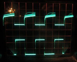
Ok here we go. 25kHz PWM signal coming out of an attiny85 MCU to a IRLZ34N mosfet via a 100ohm resistor. NPN MOSFET is switching the fan's ground wire.

First up is a 80mm .31a jobby. Lower trace is PWM signal going into the mosfet out of the attiny85 MCU. Upper trace is voltage on the ground side of the fan. 5v/divider on the top trace.

At 50% PWM:
80mm-50percent.jpg
It could look happier, but it's not too bad. Keep in mind that the mosfet is eating the negative voltage spikes with the built in diode, it may or may not appreciate this. You can see the negative voltage build up and then open the diode, that's the little square dip just a the MOSFET switches off.

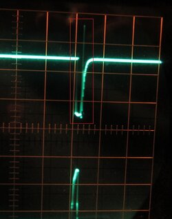
At a very low PWM percentage, there is a 17-18v spike when the MOSFET slams off and the charged coils in the fan have nowhere to put their energy:
80mm low percent 18-19v spike.jpg

Fan didn't make any odd noises however.


The second fan is a 120mm 0.48a higher RPM character, it's the highest power fan I have that wouldn't melt the breadboard, the next size up is 3.6 amps!

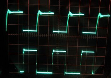
Anyway, 50% duty cycle:
120mm 50percent.jpg
Not too bad, note that some of the general mess is feeding back to the arduino and giving it some negative voltage to think about!


Higher duty cycle:
120mm high percent.jpg
Poor attiny is eating 1v every pulse, there's a lot of mess when the fan is coasting too.

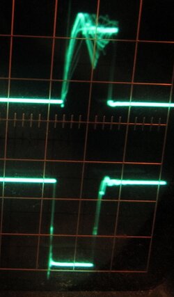
Lastly at very high duty cycle (99% or so):
120mm v. high percent.jpg
15v spike on the fan end of things, bit over -1v to the attiny.

This fan made nasty squeeling noises being switched like this, much unlike the first one that made it's normal noises only.
 
Chalk it up to inductive loading, I had some inkling about that...but wasn't quite sure how computer fans react as opposed to pure inductor, bc generally speaking, and i'm sure both you and Bing are aware of this, that Inductive kickback is something that can easily by using a diode in the reverse direction so that the kickback gets recycled back to the inductor.

I dont' like that little 1v getting sent back to my arduino tho lol Then pins can handle up to 5v but don't care to test it.

Question, with the inductive kickback from the motors, why is it that the PSU doesnt have to be protected from this surge? Is this handled internally by the fan or internally on the PSU itself?
 
At RC cars or planes as you mentioned by pwm-ing directly the power lines to the motor, its different situation, cause the pwm driver was built by design with beefy transistor and also with "adequate" protection against the inductive kick back generated by the mis-fired pwm signal on the stator vs rotating magnet/impeller.

Physically, the magnets or impeller and stator with those windings are actually quite robust and can survive this power pwm condition, it is the electronic parts that is the primary concern.

Now, the problem with ordinary fan either non pwm (3 or 2 wires) or pwm (4 wires), the primary driving circuit inside the fan's hub is not designed to cope with this kind of rude control, and might toast the components like the power mosfet/transistor. Also for 4 wires pwm fan, check this dead fans internal thread HERE, those pwm fan has much more complicated circuit than non pwm fan, and those circuit and it's components are precision and sensitive by design to be able to fire the pwm pulse precisely by the control circuit thru pwm signal from pwm wire, but "NOT" by pulsing the whole fans on and off.

Like example here pointed by LennyRhys on the note from Nidec HERE, that fan manufacturer definitely knows what they're talking about.

Also a long and abit complicated explanation on why controlling fan using the crude way by pwm-ing the power line is not a good idea, read it HERE

Anyway, if those fans are dirt cheap and there is no annoying whine or noise, then I think its worth an experiment just for fun, but when it comes to those expensive high quality fan, suggesting you not to do it, its not worth the risk.

good reads! Thanks!
 
When the fan is running full blast there aren't any spikes, or they're held internally by the fan. It's possible that the fan eases it's transistors/MOSFETs/whatever it uses to drive the coils off rather than slamming them off, it's also possible that it uses an H bridge and feeds the coils AC (more or less), or that it times the shutoff just right to feed the energy into the fan's rotating magnets. I don't really know though.

The PSU doesn't see it really, if you look at where the MOSFET connects the pin to ground again there is the tiniest of twitches, but the PSU has plenty of juicy capacitors sitting there waiting to mop things up. If it gets past that it runs into the rectifying diodes, they don't care in the slightest about a bit of negative voltage or a spike of positive voltage (they're generally rated for between 40 and 60 volts) and there it stops.
The general environment inside a PSU is really quite nasty, the only reason the voltage that comes out is even vaguely smooth is that there are an awful lot of filtering capacitors! If you check out one (or more) of the PSU reviews I've done on the front page and look for the ripple testing you'll see what I mean. Especially considering that the testing is after all the caps!

Mostly though there isn't much kickback when the fan gets to control its own destiny, or at least I'm assuming there isn't.
I may wire a fan up with a diode between 12v and the fan, then I could catch any positive voltage spikes heading back in that direction, maybe do the same after the fan and look there too.


Arduino wise it doesn't care about 1v, it's the negative 1v I'm concerned about. It's very very brief and doesn't have a lot of juice behind it, so the odds of it actually overheating and killing anything are pretty slight. I still don't like it! I may see if I can dig up a normal transistor to see if the same thing happens there.
 
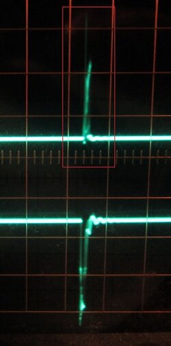
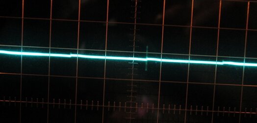
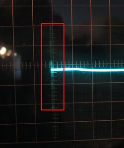
Ok turns out no diode is needed, shouldn't have surprised me. Anyway, first off here's what it looks like with the same settings as the previous shots (or the same voltage at least, different frequency I think, this is taken with the scope probe right at the fan connector, on the 120mm 0.48a fan.

120mm 100percent internal switching2.jpg

Spikes!


I switched to AC mode and dialed the voltage/divider down to 1v/divider for a better look:
120mm 100percent internal switching.jpg


For giggles I checked the 12v in various other places around the system, and the spike is strong enough to be present everywhere, that includes the PCIe connectors as well as the rest of the molex cable and such.

I think I'm going to be doing dual-PSU benching now, one to run the screamers and one to power the system.


Also, this is a noisy fan! I checked the 80mm and it has a spike, but it's along the lines of 0.08v rather than multiple volts.
 
The general environment inside a PSU is really quite nasty, the only reason the voltage that comes out is even vaguely smooth is that there are an awful lot of filtering capacitors! If you check out one (or more) of the PSU reviews I've done on the front page and look for the ripple testing you'll see what I mean. Especially considering that the testing is after all the caps!

This I definitely know, I've been guttin 2 dead PSU's for parts for the past liek 3 weeks...The things are pretty damn hard to take apart.

What kind of solder to commercial grade appliances use anyway, they definitely use stuff high temperature rated than a 30w soldering iron can handle. Im using a heat gun to melt the solder to get the dang parts off.

I think I'm going to pick up an oscilloscope to mess around with, expensive toy that I proly won't use much but still... a toy!
 
It's lead free stuff, that combined with the thick traces and large parts can make it pretty tricky to get 'em apart.
You definitely need an ozyscope, they're fantastic fun :D

EDIT:
As a side note, my Antec HCP-850W PSU is awesome. Accidentally shorted 12v to GND during the earlier testing :chair:
It shut down fast enough that I didn't hear an arc and couldn't find where it'd happened. Yay for high quality multi-rail PSUs!
 
The only thing I'm concerned about is whether I can get away with a pocket oscilloscope like the ones avail at spark fun or go with a full sized modek
 
I don't really know, I haven't used anything but my old (70s) analog scope.
I'd like to have one of the pocket flavors for basic arduino stuff at least. I don't know if the $100 flavor can cope with 200kHz to 500kHz PSU output stuffs.
 
Back