• Welcome to Overclockers Forums! Join us to reply in threads, receive reduced ads, and to customize your site experience!

Making ALL non-native PWM fans, pwm controllable via motherboard header

Overclockers is supported by our readers. When you click a link to make a purchase, we may earn a commission. Learn More.
They handle upwards of 1 MHz, I just watched a review on the tube and it looks like its best kept to under 200khz which for my uses is completely fine. In face I've found one that interfaces with my iPad 2. And since I use my iPad 2 religiously ESP when working on circuits, I'm researching that one, which right now I'm seeing good reviews
 
Quick question... Could I use D2396 transistors?

I'm still in the learning stages of circuit analysis, so any info would be greatly appreciated!
 
Quick question... Could I use D2396 transistors?

I'm still in the learning stages of circuit analysis, so any info would be greatly appreciated!

Depends on what your driving and whats driving the transistor.

Basic tip31c transistor works fine for single phase amplification. Albeit there is some heat dissipation issues you'll have to contend with if driving high ampere motors.

I drive a 1.6A Brushless using a single tip31c.
 
Pfft well that was more of a process than I though, Eagles is a bit cumbersome to use for the first time lol

Anyway:

picture.php


There are some calculations needed for the Darlington Pair, which is what the electronic world calls 2 npn transistors stacked one atop another.

We'll start with the specs of the fan:
V = 12v
I = .56amps

Calculations:
1. Know the amperage of your DC motor(s) this is what you are going to use to calculate the amount of current(I) needed to drive the OUTSIDE transistor. The outside being the transistor to the far right side.

A transistor is used to control a very LARGE current, with a very SMALL current. In this case the large current would be the .56 amps of the motor, the small current would be the weak PWM signal from your mobo.

So how it works, the MORE current you give the (B)ase of the transistor the MORE current it will allow to flow from the (Collector) to the (E)mitter. It's like a water faucet at your house. You turn the knob(takes little force) to control the amount of water that goes through...same exact thing.

How do we find this "little force" that controls the big one? Simple, if your using a TIP31c transistor...just divide .56a by 100. = .0056a

What the hell is that for!? Well that right there(.0056a) is the MINIMUM amount of current you need to supply the (B)ase of the transistor to allow ALL .56amps to flow from (C)ollector to (E)mitter... In other words. If you supply the (B)ase with .0056amps, the transistor allows all teh current to flow though it so that you get FULL POWER.

Once you start lowering .0056a to the (B)ase the transistor starts restricting the current flow and hence your current and consequently voltage, starts to drop/go down/not flow as much.

STOP.

This is actually where most people can stop! Yup, that's it. All you REALLY NEED is a TIP31C NPN transistor and there you have it a PWM controllable fan(s) via your motherboard header.

In the above schematic remove the left transistor and resistor.
1. Feed the fans RED wire 12volts from the PSU(NOT the mobo)
2. Connect the fans black wire to the transistors (C)ollector.
3. Connect the (E)mitter to ground and finally feed the (B)ase of the transistor your PWM signal from your mobo.

*The reason we stop here is the fact that your fans draw is .56A(560mA, , milliAmps). You only need .0056A (5.6mA, milliAmps) to drive the transistor, which then drives the motor. Your motherboards headers can very much source 5mA if current without even breaking a sweat. Do you see now how a small current(5.6mA) can control a very large current(560mA).

The Darlington pair chops this number down even further(.0056 / 100 = .000056A)! So now you can control a GINORMOUS load(limited by how much current your transistor can handle from (C)ollector to (E)mitter) with a TINY amount of force.

That's as far as I'll go for now, if you want to know how to calculate and use the rest of the schematic, I'll explain if needed. Otherwise, the electrical engineering folks will recognize this Darlington Pair


The design above may be improved by adding a flyback diode, more specifically a Schottky diode, between the fan connection terminals to allow the fan(s) to free-spin during the off cycle of the Darlington Pair. This will improve both low speed operation and reduce the voltage spikes you see.

Cheers,

-Tyler
 
You are most of the way to a switching power-supply...

why not put an LC filter the output of the darlingtons and smooth the signal. That way you are just regulating the voltage to the fans rather than switching them. Probably clean up the 12-spiking also. Keep in mind you are charging and discharging a coil [ motor ] by switching, we use diodes to block this in relays. This could cause a problem in some DC motors.

Just an idea.
 
Spent a bit of time on this project (or my take on it, anyway) over the weekend.
I now have a functional, properly wired, buck regulator that will quite happily power a low end (.25w, that's watts not amps) fan with anywhere from 3v (max I can get with everything at 5v starting) down to 0.1v or so. I used a 1.2uH inductor off a (very) dead gigabyte motherboard, a schottky rectifier out of a (very) dead PSU for the low side diode, and a fairly cheap ($0.75 I think) NPN logic level MOSFET, with an Attiny85 driving the operation at fairly obscene switching speeds.
Obscene enough that a 10mOhm 1000uF capacitor is (far) less effective than a 0.1uF ceramic jobby.
I think that's pretty obscene :D

Anyway, ignoring the breadboard costs I think I spent about $8 on the thing, $7 of which was the attiny85 ($2) PCB for said attiny85 ($1) and various bits to populate it.
Plus the programmer, which was $22.
What is really cool is that the Attiny has an inverted PWM output as well so it can drive a low side MOSFET!
I also have a few MOSFET drivers off a (very) dead 4870 that I've been playing with, I'm going to give one of those a try at 12 V at some point.
The difficulty looks like it is going to be getting 100% output to be 12 V. Convincing the high side MOSFET to stay on is going to be an interesting trick when using a NPN mosfet like buck regulators like. I may have to switch to a PNP and see if I can make it work.

My goal is something that can run one of my ~4 amp 120x38mm fans from full blast to down low, without risking the life of the electronics package.


EDIT:
The difficulty is that if you want to regulate the voltage to the fan you want to have your regulator on the positive side rather than the ground side.
You could do it with a PNP transistor pair.
 
Here's Phanteks's take on the concept of a PWM to voltage converter.
Full speed looses 100RPM and about a volt due to the drop going through the transistors.
0% PWM means stopped fans, so that's kind of cool. The Phanteks fans start at 2-3%.

phanteks-PWMadaptor-top.jpg
phanteks-PWMadaptor-bottom.jpg

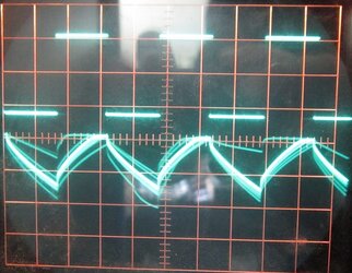
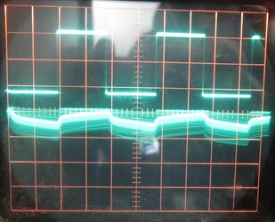
Output, top chart is 25kHz PWM frequency, bottom is 3kHz. Top line is PWM signal bottom is output voltage. 2v/div on all of 'em. zero volts for the output voltage is way off the bottom of the screen.

phanteks-PWMadaptor-PWMat25kHz.jpg

phanteks-PWMadaptor-PWMat3kHz.jpg

The varying lines on the output side show where one or both fans had a motor coil fire. You can see a couple PWM segments where neither motor fired and the voltage stayed high, as well as a couple where both fans had a motor fire and the voltage went significantly lower.
If you look more closely still you can see where a coil starts firing and stops firing also. I love scopes.


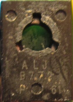
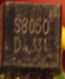
Closeups of the ICs, both are PNP BJ-Transistors.
phanteks-PWMadaptor-bigIC.jpg
phanteks-PWMadaptor-smallIC.jpg


EDIT:
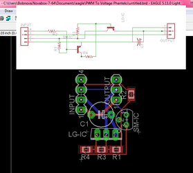
Schematic (correct, I think) and theoretical PCB layout. I'll buy the parts and try making it for giggles at some point.
PWM-Volts-Schematic.png

Parts list:

LG-IC: Halfway decently juicy PNP BJT, needs a rating of an amp at least.
SM-IC: Non-juicy NPN BJT, rating doesn't matter much.
R1: 358k All resistor power ratings unlikely to matter much.
R2: 1k
R3: 10k
R4: 1k
C1: 10uF 25v.

Function:
The smaller NPN BJT is used to control the larger one, it takes the input signal and converts it from a voltage signal to a milliamperage signal which is then fed to the larger PNP BJT, the larger BJT is always fed a little bit of power and hence conducts a little bit. Thus "off" is not fully off, which allows the use of a smaller capacitor and also removes the issue of voltage spikes (negative or positive).


EDIT: (embarrassingly long after writing the initial post...)
The small transistor appears to be a NPN, not PNP. Whoops.
 
Last edited:
Back from the deeaaaaaad!
Revisited this due to a PM I got asking if I'd built it yet. I haven't, but I'm buying parts now.
Also discovered that the smaller transistor is NPN not PNP. That's a bit embarrassing.
 
Subbed. I breadboarded another version of a pwm->analog circuit that I'll test tomorrow.
 
I had a distraction or two, I'm now buying parts for the circuit more or less as Phanteks built it (not, mind you, how I incorrectly schematic'd it...), as well as parts for an op-amp based PWM-DC converter, and parts for a switching regulator that I intend to somehow hack to take a PWM input. Not real sure how I'm going to manage that, but I'll figure it out. Or kill all the parts, that's certainly possible.
Fridays attempt resulted in a capacitor venting quite literally right in my face. Goooo Fcon...
 
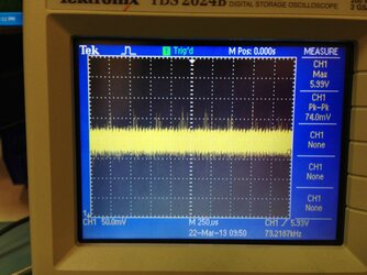
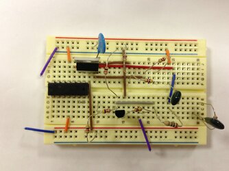
So I tested out my prototype in the lab, and after a small revision I have a version that works pretty well. It goes from 0 to about 10.7V 0->100% duty cycle. It's pretty clean too. Ripple was less than the scope noise. I may try replacing the npn with a pnp to see if I can get it up to 12V. This transistor can take up to 1A, so it'd be usable with some beefy fans.

o1Xcz0u.jpg
imvyVHs.jpg
 
Last edited:
74mV isn't much ripple either way, it's probably mostly from the PSU.
Can you post a pic of the device itself and/or a schematic? I'd like to see exactly what you've come up with.
I finally placed a digikey order today, it has parts for three or four potential ideas :D

One thing I was contemplating is a comparator and a MOSFET, the comparator to sense whether the smoothed out PWM signal was higher than 95% or so and if so trigger the MOSFET, to bypass the whole thing and give the fan the full 12V.
Rather more complex of course, but so it goes.
I spent some time a while ago working on convincing an Attiny85 to sense the frequency of an incoming PWM signal and put it out again at a different frequency. I was only partially successful.
Thinking about it, I think I'd have a much easier time taking a duty cycle and putting that duty cycle out at a much higher frequency (something suitable for buck converters).
Of course, that adds an Attiny and a buck converter, not the simplest thing in the world :p
 
Can someone help me? I just tried this with my asrock extream 4 Z77, I just used 1 npn transistor but when the system heats up the fan slows down in staid of speeding up, my CPU fan speeds up as normal.
 
Can someone help me? I just tried this with my asrock extream 4 Z77, I just used 1 npn transistor but when the system heats up the fan slows down in staid of speeding up, my CPU fan speeds up as normal.

How have you wired it up? Sounds like you've got it inverted somehow
 
Fan + to +, Fan - to collector, emitter to - and base to the PWM on my motherboard, the 4th fan pin. I checked this several times and used several different transistors but they all do the same.
 
Well for starters, the PWM signal is an open drain/collector output. You need to use a pull-up resistor. Ideally to 5V but some people do 12V
 
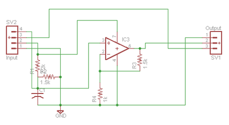
Here we go, this is working happily on my bench right now. The op-amp can be almost anything, as long as it is rail-to-rail and can handle enough amperage to run the fan(s).
As it stands it gives ~5v at 0% and 12v at 100%. Capacitor is 10µF, forgot to mark it (not overly important, I wouldn't run a smaller one though). A cap on the output is probably a good idea, but doesn't seem to be necessary at the load level I'm running with the op-amp I'm running (which can handle a full amp).

pwm-to-analog.png

Essentially part1 is a resistor divider to get ~5v from the 12v power source.
Part2 is a RC circuit to turn the PWM into an analog voltage level from ~2v to ~5v.
Part3 is the op-amp, which takes that ~2v to ~5v level and turns it into a ~5v-~12v level.

With no output cap, ripple at the mid range voltage levels (anything but max) is ~50mV. At full voltage it's ~250mV. That's not low, but a fan'll survive it just fine. A 470µF cap on the output drops that to ~18mV, well within ATX spec.

EDIT:
Op-amp is $1.24, resistors are something like $0.05 each, the 10µF cap is maybe $0.15, a 470µF 16V cap with enough ripple current rating to survive most anything is $0.32 or so.
I think all told the parts bill for a single unit is something like $3. Admittedly it'll only drive up to an amp of fans.
5 amp op-amps run $16. Ouch.

2.EDIT:
On the other hand, Intersil shows up to daisy chain op-amps for enhanced load abilities: http://www.intersil.com/data/an/an1111.pdf
The unit I'm using has two in one package, so that's 2 amps in theory. The technicality being if it gets hot and fries of course.
4 amps that way would cost $2.48.


3.EDIT: This schematic has issues. Following it directly is not advised. It needs the R half of the RC smoothing circuit on pin4 of the input connector. With that added, it works nicely.
 
Last edited:
You're much better off using a PNP as the output driver instead of the op amp. Just wrap the feedback around that instead and you can get cheap PNPs that handle plenty of current while using a cheap low drive OP amp.
 
I don't intuitively know how to wire a PNP for current control given a 2-5v analog signal to work with. Plus I like the full 12v aspect, though if there are super low voltage drop PNPs out there that'd work.
I've only really worked with MOSFETs, or with transistors as digital devices. I haven't played with their analog side.
 
Back