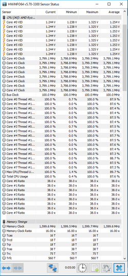
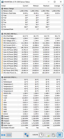
I recently updated the bios on my Asus Strix X370-F from the September build to the most recent and have been toying around with my overclock. With the September bios my R7 1700 needed 1.3875v with LLC level 5 to run stable at 3.8ghz with my ram at DDR4 3200. With the new bios, I was able to run 1.3875v with LLC level 1 @ 3.8ghz /DDR4 3200 Prime95 stable. During stress testing (realbench and Prime95 26.6) I noticed my voltage dropped to 1.325v as reported in HWinfo which got me thinking about setting my LLC to 5 and set voltage to 1.325v and test for stability (currently about an hour into Prime95 26.6 small FFT now. max temp 68C) Im just curious to get a general consensus on load line calibration on ryzen. Is running a higher level of LLC with a lower voltage better or worse in terms of longevity compared to a lower level of LLC with a higher voltage?
-
Welcome to Overclockers Forums! Join us to reply in threads, receive reduced ads, and to customize your site experience!
You are using an out of date browser. It may not display this or other websites correctly.
You should upgrade or use an alternative browser.
You should upgrade or use an alternative browser.
Thoughts about LLC with Ryzen overclocking
- Thread starter btmedic04
- Start date
- Thread Starter
- #3
yeah, the vdroop is pretty pronounced with Ryzen. even with LLC level 5, voltage set to 1.325v, the core VID's in HWinfo64 all drooped to 1.219 while under Prime95 small in place FFT load.
However with that being said, my system passed an hour of the realbench stress test with 16gb of ram usage (same amount I have) 12 hours of prime95 in place small FFTs, then a realbench benchmark run. Temps topped out at 69C. Im going to see if I can drop the soc vcore down a bit from 1.150 and still maintain DDR4 3200 speeds. Now that I have a little more voltage and thermal head room, 3.9ghz may be possible \o/
However with that being said, my system passed an hour of the realbench stress test with 16gb of ram usage (same amount I have) 12 hours of prime95 in place small FFTs, then a realbench benchmark run. Temps topped out at 69C. Im going to see if I can drop the soc vcore down a bit from 1.150 and still maintain DDR4 3200 speeds. Now that I have a little more voltage and thermal head room, 3.9ghz may be possible \o/
- Thread Starter
- #5
I found the setting to increase current percentage, however im having trouble finding reaction timing for the vrm. what are some general terms used for it? also what is a reasonable setting for an AIO cooled system? with voltage set to 1.35v, 3.9ghz isnt stable beyond cinebench R15 benchmark runs
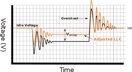
Load-Line Calibration (LLC) is a mechanism offered to overclockers designed to compensate for large voltage droops when a CPU or GPU is under increased load. The mechanism attempts to compensate for the sudden sagging in voltage by preemptively applying additional voltage. The LLC, which is part of the voltage regulator module, was introduced in order to ensure a more smooth voltage delivery when the CPU/GPU is both idle as well as under heavy load, thereby eliminating related system instability or crashes on overclocked systems. This feature is aimed at overclockers as for normal systems the LLC is usually disabled by default because typical Vdroop is part of the system specification.
Note: While extremely helpful at times, load-line calibration must be used with extreme care!
This spike, called an overshoot, exceeds the desired reference voltage. A spike in voltage that is too great will degrade the transistors on the chip. Extremely high voltage will cause a catastrophic breakdown of transistors. Companies such as Intel publish VRM specifications that specify what's the maximum allowed overshot voltage (VOS_max) and for how long it's allowed (TOS). Since motherboard manufacturers cannot exceed those ratings, there's a limit as to how high they can change the duty cycle before you exceed those ratings. Therefore it's natural for VRMs to have a certain amount of Vdroop in order to make sure they do not exceed the allowed overshoot voltage. In other words, Vdroop is intentionally added in order to prevent a voltage overshoot that is harmful to the CPU.
Reducing overshoot[edit]
There are various ways to reduce the overshoot on modern systems. The easiest way is to use bigger components that can store more energy. While this will works the efficiency is reduced. A better approach is is that the PWM Controller frequency and sampling rate can be increased. With increased sampling rate, it can compensate for voltage spikes much quicker before it spikes all the way up. It's worth pointing that increasing the switching frequency affects the circuit - the MOSFETs need to be able to keep up with the frequency, also the very high-end PWM Controllers become too expensive to use on motherboards. Eventually the design decisions boil down to a compromise. https://en.wikichip.org/wiki/load-line_calibration

I found the setting to increase current percentage, however im having trouble finding reaction timing for the vrm. what are some general terms used for it? also what is a reasonable setting for an AIO cooled system? with voltage set to 1.35v, 3.9ghz isnt stable beyond cinebench R15 benchmark runs
You can look for things like Phase Response. Sometimes they have options listed as Default, Optimized, Extreme or something like that. It should be in the same area as the Current Capacity option.
- Thread Starter
- #8
I found it in the bios. however it only gives me a range (50hz-600hz) in 50hz steps. if I change it from auto to manual, it defaults to 300hz. not sure which direction i need to go with it so it looks like im going to have to do a bit of reading to find out
No that's something entierly different. Changing the frequency timing will only increase or decrease how quickly the VRM's PWM voltage wave gets to the inductors. Its another option in there. I meant to look it up yesterday while at home but forgot.
- Thread Starter
- #11
- Joined
- Dec 19, 2012
Just curious how's the voltage swing when the LLC and other options are left on auto? I haven't found it to be too bad with the CHVI http://www.overclockers.com/forums/...n-Overclocks?p=8013662&viewfull=1#post8013662
- Thread Starter
- #14
Just curious how's the voltage swing when the LLC and other options are left on auto? I haven't found it to be too bad with the CHVI http://www.overclockers.com/forums/...n-Overclocks?p=8013662&viewfull=1#post8013662
I set LLC to auto on both the cpu and the soc, but left the VDDCR cpu and VDDCR soc to optimized and am about 20 minutes into a prime95 (26.6) in place small fft run. cpu voltage drop is .075v and the soc is .013v. I've also noticed a 7c-8c drop in temps as a result (peaked at 55.3c, currently at 54.3c) I'll have to run my full stability testing to ensure it is still stable, but so far I cant complain!
- - - Updated - - -
I would move from Extreme to Optimized, as I have found that Extreme can really put out some heat if you are not too careful. I keep my 1800x at 4.0GHz with my RAM at 3200MHz using Optimized Phase Control and a bit of a push in current.
oh yeah, extreme was getting too hot for the touch test so I backed it off to optimized and its much cooler. Im starting to think 3.8ghz with 3200mhz ram is about this chips limit as I really dont want to go above 1.35v on the cpu and 1.2v on the soc (currently at 1.325v and 1.150v)
IIRC the max for SOCv for 24/7 OC is best at 1.1V. But I could be wrong.
Check out Elmor's guide for best practices with Ryzen
http://www.overclock.net/forum/11-amd-motherboards/1624603-rog-crosshair-vi-overclocking-thread.html
He has some links at the bottom of his post to a guide he created.
Check out Elmor's guide for best practices with Ryzen
http://www.overclock.net/forum/11-amd-motherboards/1624603-rog-crosshair-vi-overclocking-thread.html
He has some links at the bottom of his post to a guide he created.
- Thread Starter
- #17
IIRC the max for SOCv for 24/7 OC is best at 1.1V. But I could be wrong.
Check out Elmor's guide for best practices with Ryzen
http://www.overclock.net/forum/11-amd-motherboards/1624603-rog-crosshair-vi-overclocking-thread.html
He has some links at the bottom of his post to a guide he created.
Thanks! according to elmors guide, recommended voltages for ambient temps are 1.4v for the cpu and 1.15v for the soc with a max of 1.45v and 1.2v
Similar threads
- Replies
- 31
- Views
- 966
- Replies
- 30
- Views
- 2K
- Replies
- 0
- Views
- 838

