• Welcome to Overclockers Forums! Join us to reply in threads, receive reduced ads, and to customize your site experience!

***Volt Mod's For AsRock SataII***

Overclockers is supported by our readers. When you click a link to make a purchase, we may earn a commission. Learn More.
Chino,

I think you summed it up well. I'm basing the overclocking abilities on the stickie here in the memory section based on the Infineon "B" series but I have no experience with any of it. Maybe the "C" series is better. From what their tech support states, they aren't guaranteeing my sticks are all Infineon C either, they really don't know themselves.

We also have to realize that probably they aren't dealing with a vast percentage of customers like us either. Most people don't care but I agree, it's a helluva way to make RAM sticks and market them.

220 - 250 MHz would suit my needs ok.
 
well im priming at 2900Mhz now. im at the max voltage of the mod, 1.55, but actually 1.583 (0.033 overvolt), so it looks like this will be the limit for me. And thats assuming it will be stable. Its looking good so far though. Ill definatly get 2.8, prolly 2.85 or higher if 2.9 isn't stable. I got this chip for $260AUD(inc postage) off ebay, an ive been most happy with it. Its a CAB2E 0546FPAW chip, so they are hit and miss for overclocking, but this one dose well. Oh, and on 33c loaded at the moment with the fan on 7v. ill have to update my sig soon....

UPDATE: 4 hours stable, good enough for me! ~5c increase in temp across the board. idle 25, load 33-34.
 
Last edited:
hey CB, out of interest, what score do you get on 3dmark 05/06? your system is pritty damn close to mine, so its a good comparison.

My ram is at like 243Mhz 2.5 3 3 8 2T now. HTT is at 290. It posted at 290 1:1, but it was fricken unstable. haven't tried cas 3 on 2t yet, hopfully it will work. then i might have a changce at 1:1. my mem bandwith according to sandra 05 is about 5300mb/s atm. Im thinking thats a little low. ill have to test, but for now im happy.

P.S: its winter here atm, my temps will sky rocket soon as it reaches 30-35c during the day here. hopefully my cooling will stand up to it. Ive always got 12v setting for my fan though. i think that will keep me outta trouble :D

P.P.S To avoid a double post i added this here. Just a bit of proof for thouse who don't believe. 3mins of prime load while doing other stuff. It stays at this temp believe, if you don't ask and i will prove it :D Ambeint temp is ~18c
 

Attachments

  • temps.JPG
    temps.JPG
    123.5 KB · Views: 186
Last edited:
Hipcrostino, sorry for the late reply, too many assignments grrr!

Anyways, here are the benchies as requested;

3dmark06 = 3307

3dmark05 = 6765

This is with default settings in 3dmark, I just installed and ran the benchmarks. You can see how the 7800GS gets crippled by the higher res and HDR + SM3.0.

My GPU got to 59°C in 3dmark05 but only got to 54°C in 3dmark06... which I think is odd.

BTW my CPU settings are in the screenies (10 x 300 = 3GHz, v1.568), you can see my RAM settings too.

Could you post your highest oc and benchies too for a direct comparison?
That would be sweet.

Regards, chino.
 
Chino,

Do you think using all 4 RAM slots holds you back any? I know there are normally some sacrifices made using all of them besides the 1T - 2T.
 
RT - a very good question! You're gonna regret asking me this... I've thought a lot about it. In relation to single core CPU's...

Simple answer; It depends on your CPU, RAM and mobo's capabilites and compatibility. If it works then there is no disadvantage.

Slightly longer answer: It depends a lot on your CPU's memory controller. There are 3 revisions, E3, E4 and E6. Which one is best with 4 sticks? Apparently E6, according to AMD, but from everything I've read it seems that revision E4 is best followed by E3... BUT this could be because some E6 CPU's are actually the faulty Toledo (dual core) CPU's with one whole core disabled, which is making the REAL E6's (San Diego's) look bad. These Toledo's (CCBWE) don't oc as well as they dissipate heat more unevenly.

Now for the long answer...

I have come to the conclusion that socket 939 CPU's are more likely to work better with smaller RAM capacities. Solely because you are removing more variables for error, by this I mean number of RAM chips.

If you look at the 3dmark fanbois a lot of them use 2 x 256MB, with high voltage and low latencies. Less RAM chips means less variables for potential problems when oc'ing and benchmarking. They reduce their odds for error resulting in exceptional oc's.

Asleep yet?

When the socket 939 CPU's were initially being designed and tested, only 256MB and 512MB sticks of RAM were available to test with (apart from some really expensive and poorly performing 1GB sticks that introduced very high latencies). So therefore I believe that socket 939 CPU's will work better with 2 or 4 smaller capacity sticks than with 2 large capacity sticks because that's what they were tested with - but again depending on the CPU revision.

The 'E' Revisions

Apparently all E revision CPU's are susceptible to errata #79,110,112,121,122,131,135, and 136. The errors only occur in very specific circumstances.

The E3 supposedly does not like 4 sticks of RAM very much and defaults to 333MHz DDR speed regardless of your RAM. This confirmed by the AMD E3 spec sheet. Have a look at the bottom line and you'll see the only options for 4 double sided sticks;

double rank - double rank - double rank - double rank = DDR266 OR DDR333 ONLY!

...although a few people have been able to run at DDR400.

The E4 revision apparently fixed some additional errata present in E3, they are; errata #113, #114, and #116
Again these errata only occur in very specific circumstances.

Errata #118 affects the E4 revision of the socket 939 CPU. Errata 118 is titled "Slew Rate Violation Causes DDR266 RDIMM Failures". It causes memory corruption ONLY when 8 dual-rank registered DIMMs are populated, the memory clock speed is 133 MHz, and odd FIDs below 10x are selected. Notice the word 'registered', this means it is only likely to effect Opterons really.

The E6 has the most fixes, not being susceptible to errata #113,114,116 and 118.

So there you go, 4 RAM sticks is fine when it works and the only thing you lose is 1T.
So unless the specific circumstances that trigger the errata occur, you won't have any problems. It's a lottery!
 
Chino,

Nice post, and no, I didn't fall asleep!

I think my Venice is an E6 but my A64 unit is down so I can't check it for sure. Bought it in December, 2005. Actually I'm sure it's an E6.
 
Yeah, AMD stopped making Opterons (all are E4) in November 2005, so it's highly likely your CPU is E6 as they swapped to only manufacturing the newer revision CPU's, which are E6 Venice's, San Diego's and Toledo's.

The good thing about the Venice core is that even if you get an E4, it is most likely a San Diego with half of the level 2 cache disabled and NOT a faulty dual core chip.

Your A64 is down? Having problems?
 
Chino,

I just checked the part number, it's a E6 as you said.

Motherboard replacement, should be here Tuesday and I'll fire it up again and try out these Kingston RAMs with some volt mods.
 
Awesome thread.
I've had the SATA2 since it first came out last year, and did the Vcore mode with conductive paint way back when.
The Vdimm mod was beyond my soldering skills.
Following the tips listed by others, I picked up a couple of mini grippers from Mouser, and a 1K 15 turn cermet pot from Radio Shack.
Assembled the parts, clipped it on and works like a charm.
I preset the pot to 600 ohms just to be on the safe side.
Gradually decreased the resistance till I hit 2.95 volts, and left it there.
Great option for those like me who are soldering challenged.
 
Hi Westmassguy, a familiar face!

Hmm... mini grippers hey? Are they the same as SMD grabbers?

How sturdy are they? If you move your PC in your car would they vibrate loose?

I want to do the vdimm mod but I need it to be done properly.

I think I like the idea of using a cermet pot over a vr with a trimmer, but is it heavy and bulky hanging off the mobo? I take it you soldered it on?
 
Hi chinobino!
Sorry, got the name wrong, should be mini grabbers.
There appear to be two types.
The ones Radio Shack sells are hook like, and are too big for the SMD solder legs.
The mini grabbers fit perfectly around the individual solder legs, and are relatively secure.
I too was concerned about having them slip off.
You can move them around a bit, but it would require some effort to rip them off by accident.
I would not recommend them for say a lan party server, or a unit that is bumped around a lot, unless you hot glued them to the IC after you clipped them on.
Just need a good magnifying glass to install them.
I bought the multi-turn 1k PC board mount, cermet pot from Radio Shack (it's tiny).
I took the two wire lead (about 12 inches long) from and old fan, soldered one end to the pot, and the other leads to the mini grabbers.
I used some heat shrink tubing around the cermet pot to insulate the solder points.
I just clipped the grabbers on, and left the pot lying on the bottom of the case.
You could always hot glue it to something for a more permanent install.
All in all, it was a lot less daunting than trying to solder something that small.
 
Thanks for the info :).

I might have to look into some good quality mini grabbers and soldering some leads to the cermet pot. That sounds like a good alternative to permanently soldering anything to the board - nice work.
 
ochungry said:
For those who are shy of soldering I have created an easy method that will work w/ the Asrock vdimm mod.
You need
#2 pencil....costless
nail file, sand paper kind is preferred..... 45cents
clear nail polish..... 99cents
nail polish thinner..... 99cents
2 plastic bottle caps. one for nail polish/thinner mixing and one to file graphite off #2 pencil.
toothpic

file about 1/4 tea spoon of pencil (graphite) into a container(I used plastic bottle cap)
in another plastic cap, mix 1:1 ratio nail polish w/ nail polish thinner( not nail polish remover). just use as much as you need. about 1 drop of each should be sufficient.
pour the polish mix into graphite powder and stir well w/ a toothpic. to reach a medium viscosity.
scrape off the clear coat from the metal ends of #2 resistor for better contact.
apply on top of #2 resistor w/ toothpic if solution is thick or w/ a brush (cleaned nail polish brush would do) if the solution is liquidy. you have your vdimm mod.
make sure both ends are covered w/ liquid graphite. wait 15 minutes and check the vdimm voltage and see if it worked. if not you may have to increase the graphite powder in nail polish mix. clean off and redo it.
wait till completely dried. Depending on the amount of graphite powder or how thick the application is, you will have 2.8 to 3.07v vdimm.
I have experimented this method and works great. I used nail polish because it will act as glue, plus it hardens the graphite.
After you have succeeded, you can apply a thin coat of clear polish on top of the mod to give it a protective coat.
Let me know if you tried it and worked for you and make any suggestion if you know of any better medium to bond the graphite that works better than clear nail polish.
#2 resistor

EDIT1:
before applying the graphite compound, scrape off the clear protective coat off the resistor's ends w/ a blade to create good contact.

EDIT2: I made some changes to refine the method.
As you can see it costs less than soldering and is very easy.
Good luck.

EDIT3: mix 1:1 gypsum powder w/ graphite(2b pencil) you will get ~3k resistance. Using the formula R1*R2/R1+R2=(3*1.2)/(3+1.2)=857 ohm. This will give you ~2.8-2.85v vdimm.
You can open any wall outlet and scrape of a bit of sheetrock from the edge in case you dont have any gypsum powder. But be careful not to electrocute yourself. use the nail file(sand paper kind, remember?) to make the gypsum powder. Add the polish mix(1:1 mixed w/ thinner) and stir w/ toothpic. stirring here is very importand to have gypsum mix w/ graphite well.
This mix helps those who just want less than 2.9v vdimm.
Believe it or not, it works. I have made several mixes and every time the result is ~2.9-3.2k which is 2.8-2.85v vdimm.
when dried completely, apply 2 coats of polish (diluted w/ thinner is ok) to protect it. the gypsum mix is porous, protective coats will prevent it from crumbling.

***********Easy Vcore Mod************

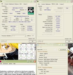
I found better location for the VID method Vcore Mod. As the screenshot shows is above and to the left of old VID mod by OCWforum. The VID4,3,2,1 are located away from the CPU bracket and are near the edge of motherboard. With this, No need to remove HSF, CPU and CPU Bracket to get to VID4,3, or VID2 to do the vcore mod (solder or use conductive paint/pen). the old location is also very close to CPU Vcore regulator and prone to accidentally shorting its pins. You solder (or use conductive paint/pen) the same Way as before. The screenshot shows VID4 w/ a solid red line over it(in case you mod VID4) and other VID's are dotted lines to indicate their locations.
The GRND pins are to the left and the VID's are to the right(next to resistors). I myself removed the old VID3 mod and soldered new VID3 location. I am using it as I am typing without any problem.
Screenshot


Greetings,

Great guide ochungry. I want to do your easy no solder Vdimm mod on my DS2. I'm going to be using some Corsair ram with BH-5 chips on it so they are pretty voltage hungry.

Is it possible to use a conductive pen instead of your graphite/gypsum mixture on resistor #2 or will this give to much voltage...?.

Or could I use a conductive pen to do the 3.2 Vdimm mod as described in this link at the top of the page where the Red solder pad is bridged to the Vdimm pad.

http://www.techpowerup.com/articles//overclocking/voltmods/130/3

Thanks in advance,

PCGeezer.
 
Last edited:
PCGeezer said:
Greetings,

Great guide ochungry. I want to do your easy no solder Vdimm mod on my DS2. I'm going to be using some Corsair ram with BH-5 chips on it so they are pretty voltage hungry.

Is it possible to use a conductive pen instead of your graphite/gypsum mixture on resistor #2 or will this give to much voltage...?.

Or could I use a conductive pen to do the 3.2 Vdimm mod as described in this link at the top of the page where the Red solder pad is bridged to the Vdimm pad.

http://www.techpowerup.com/articles//overclocking/voltmods/130/3

Thanks in advance,

PCGeezer.
Conductive pin/paint should work fine. it will give you 3.05v (final output).
The 3.20v mod works good too. for the 3.20 mod, make sure the clear acrilic coat on that big soldering pad is scraped off good. wash it w/ alcohol and cotton swab(ear Qtip).
 
ochungry said:
Conductive pin/paint should work fine. it will give you 3.05v (final output).
The 3.20v mod works good too. for the 3.20 mod, make sure the clear acrilic coat on that big soldering pad is scraped off good. wash it w/ alcohol and cotton swab(ear Qtip).

Thanks for your reply ochungry. I ended up doing the 3.2Vdimm mod and it worked like a charm. My BH-5 is now running at 2-2-2-5 1T 210Mhz when before the mod it would'nt outrun a geriatric turtle....LOL. The temp of the BH-5 is even cooler than my G.Skill LE TCCD that's at 2.7V Vdimm on my other DS2.

I've also done your Vid4 mod in your new location to both my DS2's and those mods worked great also.

Time to really see what this stuff can do now. Thanks for your help.

PCGeezer.
 
Back