• Welcome to Overclockers Forums! Join us to reply in threads, receive reduced ads, and to customize your site experience!

600lbs Steel I-Beam Desk/Computer Build

Overclockers is supported by our readers. When you click a link to make a purchase, we may earn a commission. Learn More.
I think the plan was determined to be Large Front Door+Friends+Beer (my contribution)=Inside. The gentleman apparently has some good friends. :thup:
 
Yes a large front door that opens straight into the room it's going into is the only reason it's as big as it will be

Sorry for the lack of updates. I've been gone on work in Fiji (can't complain) and have been super busy since getting back. I'll be working on it this weekend and will have updates.

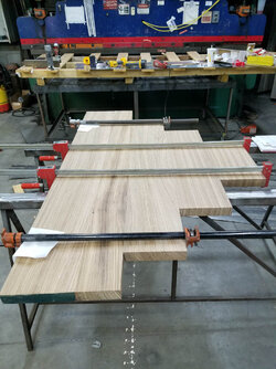
I did get the top glued together and will get that cut this weekend. I also started laying out the cooling components and will start drilling holes for the pipes this weekend.

I ended up upgrading the psu to a 1600w to give more headroom for quieter operation.
Pics will come. :)
 
If you're going to go overkill build you might as well include the PSU. It's not going to help, but it's not going to hurt either. Lol
 
UPDATE

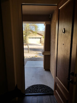
I finally had some time today to work on this project. I also got a shot of the door it's going though for you all to see. HA It is taking me a lot longer to get everything laid out than I thought. I haven't even started on the actual computer components yet but I have a really good idea of what I will be doing for the coolant components.

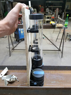
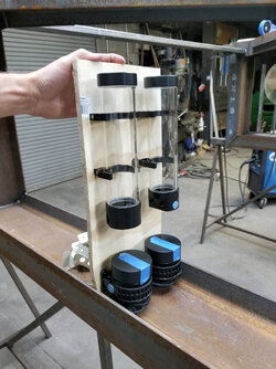
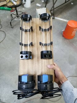
I ended up ordering 2 more 250mL EKWB Res. and 2 more D5 pumps for the loops. I measured out the total run on each loop and it is around 29ft not including the distances it flows through the radiators. I will be building two of the res/pump boards that you can see below. One on each side of the desk. This should allow for the coolant system to maintain the correct flow throughout the entire loop. If anyone thinks this is a bad idea please let me know. Each pump will be right before either a radiator or a cooling block and all 4 will be controlled the same based off the CPU fan output header on the mobo. However I am wondering if there is a way to have the loop for the GPU's be controlled based off the GPU temps? Do you know how this can be done automatically?

Onto the pictures!

1. I was able to glue the two sections of the top together so it is now one solid piece. I will be taking this to get trimmed tomorrow.
Desk-26.jpg

2. My doorway.
Desk-27.jpg

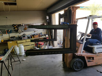
3. Moving the frame back into the workshop. It can be lifted by hand but if you have a forklift, why not use it!?
Desk-28.jpg

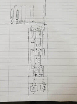
4. A rough sketch for the plumbing. Looks really complicated in that drawing but it makes sense to me.
Desk-29.jpg

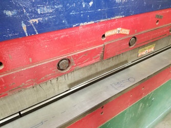
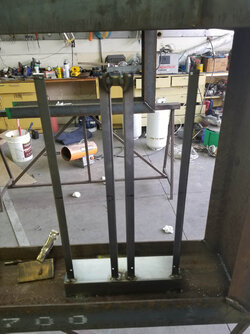
5. Bending the radiator pedestal to allow the radiators enough clearance to run pipe underneath them.
Desk-30.jpg

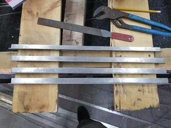
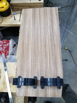
6. Radiator mounting brackets which we custom cut and bent.
Desk-31.jpg

7. Test fitting the mounting brackets. These will be painted black to match the radiators.
Desk-32.jpg

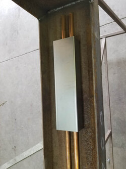
8. Radiator pedestal in position. Ran the copper pipe underneath to see how it looks/fits.
Desk-33.jpg

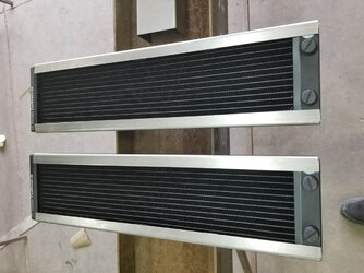
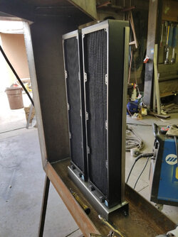
9. After tack welding the radiator brackets, I test fit the radiators to ensure they were straight and still fit.
Desk-34.jpg

10. The fans will be mounted to the backside of the radiators and blow the air away from where i am sitting.
Desk-35.jpg

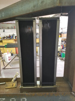
11. Final welds in-place. Once the radiators are screwed in it is actually really sturdy. I'm not worried about them going anywhere. Again all this silver will be painted black to match the radiators. I think it will look nice when done.
Desk-36.jpg

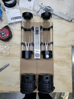
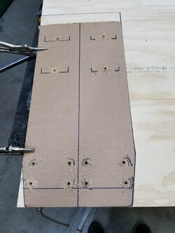
12. I traced the inside of the I-Beam onto a piece of cardboard and then cut it so it would fit inside the I-Beam. Then I started laying out the pumps and res. I also bought a slide-style flow-meter. I'm not 100% sold on it yet and not 100% sure where to put it. This is one idea.
Desk-37.jpg

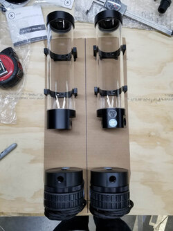
13. Here is the same layout but without the flow-meter. Which do you like more?
Desk-38.jpg

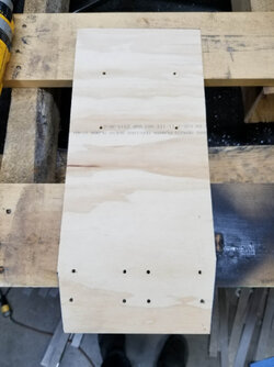
14. After lining everything up and drilling out the holes on the cardboard, I transferred it over to a 3/4" thick plywood sheet to see how it fit. The final version will actually be a 2" thick piece of the Zebra Wood that was used on the top of the desk.
Desk-39.jpg

15. The cut has been made and all the holes drilled into the wood.
Desk-40.jpg

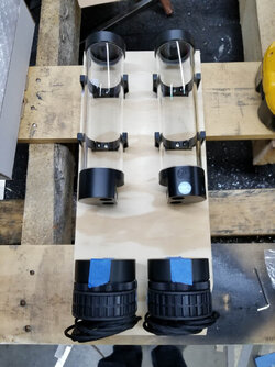
16. Pumps and res mounted to the plywood.
Desk-41.jpg

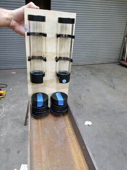
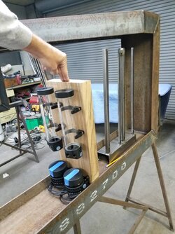
17-19 Here is what it looks like on the leg.
Desk-42.jpg
Desk-43.jpg
Desk-44.jpg

My goal is to be able to move the desk to my house by this coming weekend. Once I get these pump/res mounts built I will start laying out the computer components. Once that's done I will start laying out the piping and drilling the holes for that to pass through the I-Beams in a few places. I will have 4 drain's and 4 fill ports. 2 of each on each loop. That should aid in bleeding/filling/draining since this thing is going to be a pain to move and bleed.

More to come in the next few days!

Josh
 
I'm really diggin this build JL. I think I like the flow meter. Don't think I've ever seen that type before. Looks pretty cool.
 
I was going to ask if the forklift will fit through your front door but then you have a fork lift and I didn't see that coming. Your welds look awesome. This is a beast to say the least. I'm eager to see how this turns out.
 
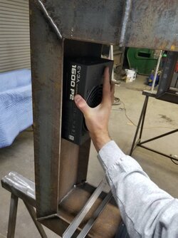
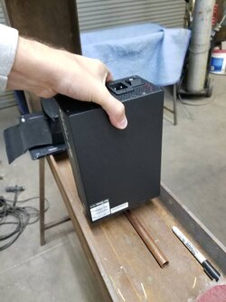
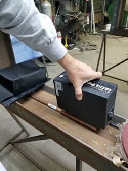
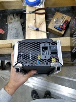
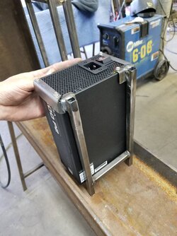
So small update. I'm working on the side where the computer components will be and having a hard time deciding where to put the PSU. It's HUGE and I have an idea where I want to put it but. It 100% sure. Thoughts? All 3 spots would require a custom made bracket to allow the PSU to float above the piping that will run under it. The second image is my favorite so far. I would just need to keep it high enough that I can run the cables under it and have enough room to safely bend them without pushing on the piping or figure out a different route for the piping to not interfere with the cables. Hmmm a1114ab89eaaf7c590d26499431df6e2.jpg 2433cf4dc32b8efcc12f42acfdf7f1a7.jpg 80f0c5c5be46d3dd19281e105a6c815f.jpg

 
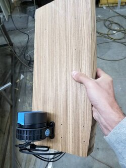
I got more work done today other than just figuring out the power supply location. I bought and cut additional zebra wood for the pump and reservoir mounts. I also completed mounting two of the four pumps and reservoirs. I am going to compete one including pumping before starting the second one just in case there is something I missed.

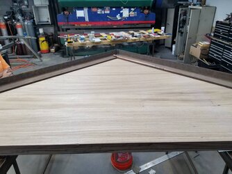
I also got the desktop cut and trimmed to fit into place. I am really excited about how it looks. I think it will look awesome when stained.

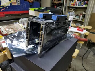
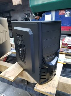
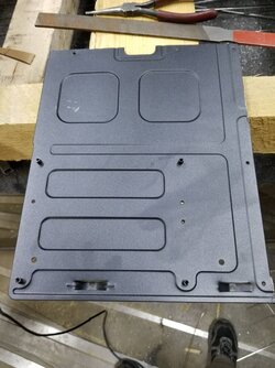
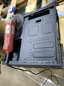
For the motherboard tray, I purchased the cheapest ATX size case I could find locally and cut the tray out of it. I'll be designing a mount for it tomorrow and will weld the tray to the frame. I also decided that I am going to mount the GPUs in front of the motherboard instead of on it. I think it will look better this way.

Now for pictures. More to come tomorrow. 7c06f609399b7a0d33d10ca8aeffefb8.jpg 0c60eab3f813ac5bc695ba99e07c7a43.jpg 4579112a9087e1c69f8b764f14891ce0.jpg 640e71c6df80c721c3d84d42cdc2e065.jpg 0338233af1f49faf8a05654f625359ae.jpg 040f347e3f9e874d66240400a32aa355.jpg 4811f3435f9c445a5978b1580656e9ad.jpg 1f9a38950da2dcab086dc1f6981ede99.jpg deddefd0e8fcb3805e7bbf3ee79271ed.jpg

 
Thanks for the updates JL.

For the PSU location I think I like the first image the most. Also, if I may offer a suggestion with your motherboard tray, it would be a good idea to make a cutout behind the CPU so that you can access the CPU cooler bracket. All higher end cases feature this and I've found it extremely helpful to not have to dis-assemble everything when doing anything with the cooler (Re-TIM etc).
 
I also like the first PSU location pic best.
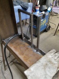
I do too but my only concern is more an aesthetics one. It will be covering the 4 copper tubes running up that part of the desk to transfer the coolant to the radiators. I don't really want to hide them. Also I would need much longer power cables to reach components. I'll get the mobo tray mounted today and then make a decision.

 
Got a good amount done today.

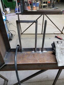
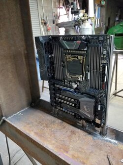
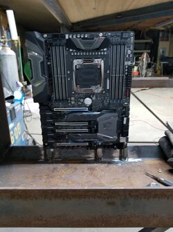
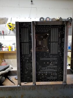
Finished the motherboard mounting brackets. Decided to just do the 3/4" steel tubing to match the way the radiators are mounted. It also allows access to the back of the motherboard to remove the waterblock if need be without removing the entire board (thanks for pointing that out to me earlier. That was an oversight on my part).

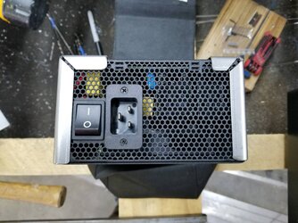
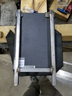
Now that the motherboard is done I started working on the PSU mount. I decided to put it in the space between the motherboard and the pump/reservoir board (not yet mounted). I raised the PSU roughly 1.75" off the bottom of the I beam to allow the coolant lines to run underneath to the pumps and also allow enough room to have the cables plugged in. I designed the holder to allow me to slide the PSU out once the bracket is welded to the desk. I don't think I'll have any issues with it. I needs 3" of clearance to slide it out. This will be good because it will allow enough room behind the GPUs for power and for the SATA cables to come out from the motherboard. I'll be welding the PSU holder in once I know exactly where/how the GPUs will be mounted. I'll start on that tonight after dinner.

It's all coming together! Yay! b87ff49dc397ba636cb7f7397084d51b.jpg f10dae9fc34b7e100906c875eefbb0b8.jpg 75e0bd3e2c8ba76a6c0283f2e0bc9ef0.jpg a1cc276a362d10d6cc9fe41b8a0b6636.jpg 87a44707bd45d973da29eed4a8960d45.jpg f149979d9b6a41b81f2f4573a6e8aea0.jpg b4fcb2a9a49eef21db0db3d135832847.jpg 95ecf04351d578579d53e0f7b4980b16.jpg 4c2943e478f6a48be1dd4a7cc7e1b3d9.jpg

 
Back