• Welcome to Overclockers Forums! Join us to reply in threads, receive reduced ads, and to customize your site experience!

FEATURED Building PWM Controller for 4 wires PWM fan

Overclockers is supported by our readers. When you click a link to make a purchase, we may earn a commission. Learn More.
Swap the two outer wires on the pot, that'll change which direction you have to turn it to raise/lower.
How exactly you're going to manage that I don't know though.


I used everything exactly as-is from the 556 circuit posted on the front page, I can check the frequency with a scope sometime this week and let you know though.
 
That's an interesting concept, I have some metal plate at that shop I could use to make a stiffening plate.

Post pic of the plate once you've made it will ya.

On a side note I made things super compact in case I wanted to stuff an attiny85 and digi-pot in on the other side there. I may still do it, but I need to test the digipot and see if it'll go low enough resistance wise to trigger full stop on the fan.

Just an idea Bob, once you've figured out the exact pot's adjustment where the fan stopped rotating, mark it down at your firmware and if still there is spare in port at your arduino, make it the 3rd button that if pushed, your firmware will jump to that exact adjustment point to stop the fan rather than keep holding/clicking the down button. This should be easy to code at your firmware and will be really handy.

I built the controller again at breadboard specifically to test the Nidec fan which is the same as Bob's. I tried it with a selection of pF caps (270-680) to change the PWM frequency but the fan wouldn't stop at low duty cycle. Out of interest Bob, what PWM frequency are you using for the Nidec fan?

It's not got that annoying high pitch squeal that the San Ace fans have, but at lowest rpm the fan motor is pretty loud and too annoying for daily use.

It's interesting that my PWM controllers/fans always behave differently from the ones that other members are using! WHAT GIVES!!

Yeah, prolly your diy circuits are cursed LOL :D ... j/k

Seriously, I begin to suspect the psu is the culprit behind all your weird experience with this circuit, have you tried with other power source ?

Also re-check again your ground lane, the fan's and the circuit's ground wires should be solidly connected, if they're connected by twisted two wires, solder it, cause sometimes this kind of poor connection will create weird problems that could make even a senior EE will scratch his head for quite sometimes if they didn't aware of it. ;)


Hey inVain, :welcome: to OcF !! Btw, he is the one who made this circuit at our local community here in Indonesia.

Selamat bergabung, tumben bisa terdampar disini ? Yep, saya bvi di kampung halaman ! :D

That is a great implementation, btw, show us the other shot that its mounted at the pci slot, this should inspire others. :thup:

Btw, glad you've bought that delta, I see you finally grabbed one of this monster at chip classy, glad to hear this.

About the wrong adjustment direction, as Bob said, just swap those 2 outer pot's pins, from that pic even I can't see it the solder side, this should be easy by moving or crossing the 2 wires that are soldered at the pot's pins at the pcb side.
 
Last edited:
16.6khz PWM signal.
Full low is a 526ns low with a 60,350ns high, for %00.8715824.
The fan wakes up at 5,610ns low, so a shade less then 10%

Also, you can cause a short that gets the 556 hot enough to turn hot glue into gel and it will still work afterwards.
Pretty impressive.
 
Also, you can cause a short that gets the 556 hot enough to turn hot glue into gel and it will still work afterwards.
Pretty impressive.

:rofl:

They are resilient little chips for sure. I must have blown up about five caps while tinkering with these controllers and the ICs all worked even after that. Only IC I killed was with the soldering iron... :bang head
 
Swap the two outer wires on the pot, that'll change which direction you have to turn it to raise/lower.
How exactly you're going to manage that I don't know though.

damn, guess I'll have to use the hard way:bang head


Hey inVain, :welcome: to OcF !! Btw, he is the one who made this circuit at our local community here in Indonesia.

Selamat bergabung, tumben bisa terdampar disini ? Yep, saya bvi di kampung halaman ! :D

That is a great implementation, btw, show us the other shot that its mounted at the pci slot, this should inspire others. :thup:

Btw, glad you've bought that delta, I see you finally grabbed one of this monster at chip classy, glad to hear this.

About the wrong adjustment direction, as Bob said, just swap those 2 outer pot's pins, from that pic even I can't see it the solder side, this should be easy by moving or crossing the 2 wires that are soldered at the pot's pins at the pcb side.

thx bing,
wow you did a great job here:thup:

hihihi....desperate perlu banyak inspirasi dan sharing project :D

yep, just after I found the datasheet of the delta, I made the deal with the seller.
and like your post on the previous page, it really sound like a jet plane :LOL

just to answer my couriousity, am I doing the right wiring on the PFC1212DE?
black = neg,
red = pos,
blue = rpm sensor,
yellow = pwm

well, guess I need to rewire the pot...
sucking solder is such a pain in the arse but now at least I got the clue, which parts that I should put to a socket:)


okay, so here's the other shot (let's forget about the shoes on the picture :lol)
22032011396.jpg


just drill a hole on a spare PCI slot and it's done, put a small knob to make it perfect:D

a few notes after building the first one:
1. use the "L-type" 4 pin connector on the next project
2. use sockets to connect the wire to the pots
3. use sockets to connect the frequency caps
4. I'm wishing to have a smaller pots:santa:


I'll share my progress with you later, guys:)
 
Last edited:
Very nice!

There's another alternative, if you rotate both zener diodes 180* that should have the exact same effect on things.
Might be easier then rewiring the thing to just desolder and resolder those two parts.
 
Thanks for the info Bob.

@ bing, yeah I think my circuits are cursed! I doubt it's the PSU though - I made sure and bought one of the best ones available, and it's a very good unit with solid and accurate voltage rails.

Re. grounding the fan, every time I put the circuit together I put the ground from the fan in series with the circuit. Surely this won't cause all the problems?
 
Make sure it's a big fat beefy ground, I split the ground plane right after it came into the board, nice fat wire to the fan connector and then a thinner one that goes into the controller circuit.
 
Yeah Bob I have two wires going to ground, and they are solid core wires so should easily be able to handle the current.

Incidentally, I was testing the fan again and the PWM wire came loose and the fan quickly shot up to full speed, devouring a bag of capacitors that was sitting on the table. One of the cats just about had a heart attack LOL.

Amazingly, the fan is totally fine, but I have yet to find the caps which were sent around the living room like a flurry of bullets :D
 
lol, that's hilarious!
My fan ate a cable last night, shaved a bunch of the insulation off but didn't really seem to mind all that much.
 
Very nice!

There's another alternative, if you rotate both zener diodes 180* that should have the exact same effect on things.
Might be easier then rewiring the thing to just desolder and resolder those two parts.

thanks Bob,
I think I'll did it this way;)
 
Another version for purist who wants pure 0% (zero percent) up to 100% duty cycle. All connections to power (molex) and fans are the same as above circuit.

View attachment 88564

This circuit has an additional IC called comparator, it uses LM311, you can change it with other popular comparator ICs like LM393 or LM339, although the pins assignment are different, just map them accordingly.

bing, is this okay?
if I add a 4.7uF caps right next to C2 and C3?
and if I put another 4.7uF+0.1uF right next to the IC1 will it hurt something?

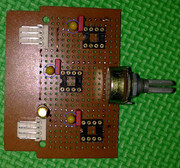
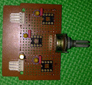
well here's my current progress for this controller:
pcb.jpg
(click to enlarge, but be advise; this is a gigantic pic)

please notice the blue cirle line, will it be allright if I let those tantallum caps over there?
I'm expecting a more stable supply for the ICs by putting them there...

thx in advance:)
 
Last edited:
inVain,

That is a really nice layout you got there. :thup:

No problem with those additional bulk caps you added for each ICs, actually they will improve the overall circuit's performance. Also I can see you're using tantalum instead of ordinary cheaper electrolyte cap which is considered inferior, nice job there.

Great ! Another OCf-er took the dive on 0-100% version. :clap:
 
bing, is this okay?
if I add a 4.7uF caps right next to C2 and C3?
and if I put another 4.7uF+0.1uF right next to the IC1 will it hurt something?

well here's my current progress for this controller:
pcb.jpg
(click to enlarge, but be advise; this is a gigantic pic)

please notice the blue cirle line, will it be allright if I let those tantallum caps over there?
I'm expecting a more stable supply for the ICs by putting them there...

thx in advance:)


Man....

One day I will learn how to put the circuits down as cleanly as that.... Maybe the I can graduate from having velcroed the prototype board with the circuit on it to my desk so I can use it on my benching rig....
 
Seriously, those are some very impressively clean layouts!
What does the bottom look like?
 
inVain,

That is a really nice layout you got there. :thup:

No problem with those additional bulk caps you added for each ICs, actually they will improve the overall circuit's performance. Also I can see you're using tantalum instead of ordinary cheaper electrolyte cap which is considered inferior, nice job there.

Great ! Another OCf-er took the dive on 0-100% version. :clap:

great!
I'm so glad to hear it....
guess I'll just proceed with the resistor and more wiring:)


Man....

One day I will learn how to put the circuits down as cleanly as that.... Maybe the I can graduate from having velcroed the prototype board with the circuit on it to my desk so I can use it on my benching rig....

mate, I'm sure you will do better than I did:)
As in my case I learned the layouting stuff mostly from the audio DIY-ers spread all over the net.
keep improvise, and just do it :rock:

I'm currently using my first prototype ne556 to control the Delta PFC1212DE inside my case,
I'll share the pics here while it's sitting inside the case, but first I gotta wait till my nice come home (I need to borrow her cell, while mine's sucks to take picture LOL)


Seriously, those are some very impressively clean layouts!
What does the bottom look like?

thx Bob,
I hope this will stay clean after I added all the resistors and caps:D
yep this one just a half finished yet, still got some parts to add...

since you ask, so here's the bottom view:

(click to enlarge)

still a rough one,
I'll try to give connection map right after I finished it as a complete and working project...
wish me luck:attn:
 
so here's my ne556 when it's sitting inside the case:


(click to enlarge)


be careful with the underneath of the PCB, so I used a recyled gsm card as an insulator.


(click to enlarge)

I'm just taping the insulator to the controller body, I'll think a much politer way to secure it latter :D


(click to enlarge)


and here's a better view

(click to enlarge)

thx to the compact design that Bing's gave us,
this controller is easy to use, and surely do nothing harm to the appearance of my rig:)
 
Just love the way you insulate the soldering side of the pcb using that unused sim card, I might steal this idea. :D

Thanks for sharing this, very good and nicely made and installed. :thup:

Btw, expecting to look for the result on the 0-100% version, again, thanks inVain.
 
I'm not liking this new guy inVain.... He just comes in here and drops those professional looking circuits on this thread... Makes me feel more of a noob than I really am.

:rofl:

Seriously though.... I'd love to be able to put these circuits down on pcb half as cleanly as you have my man... but unfortunately; all my attempts have ended up with mangled pcb and components being thrown at the wall in my office and me needing to take a couple aspirin to get rid of the massive headaches... I guess I just have to keep on killing parts and destroying pcbs until I reach that level of skill...

:thup:
 
Just love the way you insulate the soldering side of the pcb using that unused sim card, I might steal this idea. :D

Thanks for sharing this, very good and nicely made and installed. :thup:

Btw, expecting to look for the result on the 0-100% version, again, thanks inVain.

it's u and BF who started this whole thing happened;)
and sure, just fell free to use the "insulation thing", and share the version of your's will ya;)

well the 0-100% version didn't work,
I think screw something up, (hopefully the ICs :D),
gonna do some check toningt:)


I'm not liking this new guy inVain.... He just comes in here and drops those professional looking circuits on this thread... Makes me feel more of a noob than I really am.

:rofl:

Seriously though.... I'd love to be able to put these circuits down on pcb half as cleanly as you have my man... but unfortunately; all my attempts have ended up with mangled pcb and components being thrown at the wall in my office and me needing to take a couple aspirin to get rid of the massive headaches... I guess I just have to keep on killing parts and destroying pcbs until I reach that level of skill...

:thup:

just don't throw that PCB on me will ya :rofl:

well, after being to serious with the layout . I finnaly end-up with a non-working unit:bang head, yup the 0-100% project just failed me.
I'll try to get some shot at it, I have something to share that might interest you guys tough:)

n' bout the layouting thing,
I guess it will depend on how are you gonna mount the pcb, as in my case, I'd like to mount it on the rear PCI cover slot, so I must place the pots on the outer most of the PCB, and then I choose where the headers will take place . believe me everything will be easy from there, just be sure to gave some space for the components and the wire to connect to each other . and you'll be fine (don't solder the whole thing first yet though)

and believe me, I had stole lots of others ideas too to build those pcb;)
 
Back