• Welcome to Overclockers Forums! Join us to reply in threads, receive reduced ads, and to customize your site experience!

FEATURED Building PWM Controller for 4 wires PWM fan

Overclockers is supported by our readers. When you click a link to make a purchase, we may earn a commission. Learn More.
Took delivery of MOAR pwm fans today, and as usual they are different...again. I have an AFC1212DE which is whisper quiet, very low RPM at 0% duty cycle; and I have a Nidec TA450DC which is 1300rpm at 0% duty cycle. Both came from a Dell Proliant server.

My other TA450DC is 850rpm at 0% duty cycle, so I can't pair them up :( and my other AFC1212DE is a little noisy at 0% duty cycle.

One thing's for sure... with all these PWM fans I need more 0-100% channels!
 
One thing's for sure... with all these PWM fans I need more 0-100% channels!

Ones will never have enough PWM fan controllers when it comes to the "Brotherhood of Crazy Fan Collectors" . :chair: :rofl:

Lenny, that is a really nice front panel you've made there, definitely top quality, love those knobs look, really, top quality workmanship. :thup:
 
Haha thanks bing, I'm very honoured to be a member of the "Brotherhood of Crazy Fan Collectors" :D

Here's a quick vid of the controller.

PS Am I right in thinking that to change the frequency of the 0-100% 556/311 controller, only C1 needs to be changed? I was considering using a selection of caps on a rotary switch for selectable frequency without having to manually pull out and insert caps of different values... :)

 
hey Lenny, your controller looks great.
It's a good idea to add some channels for 3-pin fans.
Can you post the the voltage regulated channels schematic ?

The NE555 datasheet describes how to calculate the RC element.
C1 needs to be changed, but you can also experiment with R1 and R2.
 
Thanks for that gabomuc.

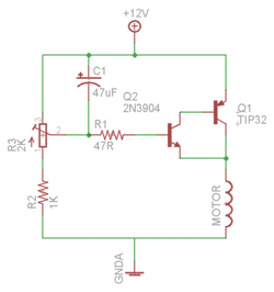
As for the 3-pin fan controllers, just a compound transistor pair on each chanel. I have tested this circuit extensively and I love it.

I'm using BD912 for Q1, and 390R for R2. The voltage range is approx 3.5v - 11.3v, which is an impressively low drop given the input voltage is a very stably 12v. A heavier load of about 2A drops it further to about 10.8v, which is still impressive, better than I got from the expensive LT1084 adjustable regulator (10.6v max).

I also left out the capacitor as I didn't need kickstart, but I may add it later.

Let me know your thoughs (despite the tangent). :D

ep8.gif
 
Thanks for that gabomuc.

As for the 3-pin fan controllers, just a compound transistor pair on each chanel. I have tested this circuit extensively and I love it.

I'm using BD912 for Q1, and 390R for R2. The voltage range is approx 3.5v - 11.3v, which is an impressively low drop given the input voltage is a very stably 12v. A heavier load of about 2A drops it further to about 10.8v, which is still impressive, better than I got from the expensive LT1084 adjustable regulator (10.6v max).

I also left out the capacitor as I didn't need kickstart, but I may add it later.

Let me know your thoughs (despite the tangent). :D

thank you.
Two of my AFB1212SH fans are 3-pin like those in your video.
The circuit looks interesting. According to the BD912 datasheet it should be possible to connect two or even more fans per channel. This is exactly what I was looking for. My only concern is that the power transistor could get very hot. Will a standard TO-220 heatsink be sufficient or should I take a bigger one for this build ?
 
Heh yea the BD912 is a bit of a beast and with a good heatsink it'll handle very high current. The AFB1212SH is only 800mA rated and about 700mA at top speed so you could easily put 2 of them per channel.

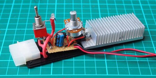
Here is my "prototype" controller which has a 220uF cap too. I made the heatsink myself, cut from an Xbox heatsink :)

xrce.jpg

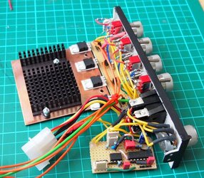
And here's the heatsink I used for the 4-channel version. It's a 75x75 sheet of 1.2mm copper with an aluminium heatsink fixed to it. I can upgrade the hetasink later as the copper is AMAZING at taking the heat from the transistors. I used Akasa thermal tape to stick the transistors to the copper sheet... very, very strong and thermal conductivity is also very good.

zhnp.jpg
 
Last edited:
of course, I also prefer the "analog style".

Varcap sounds very interesting.
Thanks for giving this idea.

What do you think about using a VCO instead of the RC element ?


sorry,
last week's been really hectic.

keep everything in "KISS" fashion and it will be fun,
start from the very basic function and you'll see things to be improved during the progress :thup:

as for me, I think I'll be focused on the current 555+311.
since "I'm this close" to make a perfect 9SG controller (well.... that's my line since last year, if I'm not mistaken :chair: :D)


Lenny,
that Alphacool is super cool :drool:
and your Nidec has zero noise too :shock:
it makes me start the vid over again to see if the fan was actually spinning, and it was :rofl:

so thick cooper had very nice thermal dissipation,
that's interesting.
I know I'll be learning lots of interesting stuff from this "crazy brotherhood" thread :chair: :D

well, that's a pretty nice front panel of yours.
and that black heatsink,
is that salvaged from a graphic card?
looks real nice :thup:
 
inVain, yeah the two TA450DC I have are both super quiet... it's just a shame the other one doesn't go lower than 1300rpm at 0% :( Nidec IMO have the best fans - the bearings on these TA450DC are crazy, so little friction just like the Gentle Typhoons, and this is definitely part of the secret to low noise. I think the TA450DC is very quiet until about 1100rpm but this is with my case open and my head right next to it. Best fan ever IMO.

And you are correct - the black heatsink is from an ATI X1300. I would like to find a bigger/taller heatsink for running 8-10amps through the transistors but this one will do for now. :D

Back on topic, I have a plan to make another controller in the next couple of weeks, this time 4 channels 0-100% 556/311 and I will be able to hook up 3x 9SG at the same time. :attn:
 
PS Am I right in thinking that to change the frequency of the 0-100% 556/311 controller, only C1 needs to be changed? I was considering using a selection of caps on a rotary switch for selectable frequency without having to manually pull out and insert caps of different values... :)


oops,
was too busy watching the vid and missed the rest of the post :D

yes, the frequency can be easily changed by subbing C1.
changing the whole RC network will be better, but swapping C1 quite ok.
heck.... now I'm thinking about changing the whole R/C network on my controller, LOL.

and again, using the rotary switch was quite an idea.
just please be advised, that by using a regular "break before make" type swicth will make the controller lose a working frequency for a while.
my best bet, the fan will run at their full speed between the switching process.

you can use the "make before break" type switch to solve the issue,
but here where I live, these kind of switches were quite hard to find and pricey.


8-10amps :shock:
I think something's worth to wait :popcorn:


I'm currently running my controller with C1=820pF, and quite happy with the result.
now since we mention about changing the whole R/C network,
I probably will try that too, then start making a new controller with the best R/C result.
subbing R3 and R4 with a pair of 10k trimmer was on the list too.

I'm thinking about a 5 channels controller; 2 pwm channels to drive 9SG in two groups, and 3 regular channels to drive a bunch of PAPST, WFB and EFB.
we'll se if I can put them together on a single board or split them onto 2 separate PCB.

knowing that huge cooper land works as heatsink really inspired me :thup:
 
Heh nice to share ideas. Are you using linear voltage regulators for your regular channels? I have the LT1084 but I must say I prefer the transistor pair because of the simplicity.

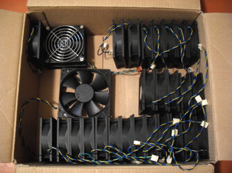
I realise now that I have SO MANY PWM fans so I have to build a controller with this function only. I now have 13 beast 120mm PWM fans:

AFC1212DE x2
TA450DC x2
TFC1212DE x2
FFC1212DE x3
VA450DC
9SG x3 :rock:
TY-140 x2
TY-143 just bought :bday:

Wish me luck :D
 
I realise now that I have SO MANY PWM fans so I have to build a controller with this function only. I now have 13 beast 120mm PWM fans:

Ones will never have enough beastie fans in the Brotherhood of Crazy Fan Collectors. :attn:

I guess its time to refresh/update your -> "Sins list". :chair:
 
Last edited:
Ah yes, I really need to take a picture of my updated collection. I also got a WFC1212B recently. Love me some Delta action!

@sandrat, if you have any trouble with PWM and kickstart it would be worth posting here. I tried to send you a PM but your inbox is full!
 
Understanding the circuit

Ah yes, I really need to take a picture of my updated collection. I also got a WFC1212B recently. Love me some Delta action!

@sandrat, if you have any trouble with PWM and kickstart it would be worth posting here. I tried to send you a PM but your inbox is full!

Very well. I have assembled Bings 0-100% + Kick Start circuitry on a bread board (my second circuitry project ever). I want to understand the operation of the Kick Start circuitry, so that I can understand the method the two NPN transistors are connected.

My issues with the circuit may be as simple as incorrect resistors, which will be rectified in the next few days. I don't have a method of confirming resistor values, and colour identification charts are of no use to me as I am colour blind.
 
It could be the value of the resistors, and it could be the way the transistors are connected (base, collector and emitter can be very confusing on these small packages...).

When confirming resistor values I use a cheap digital multimeter - you simply can't go wrong with it. I find the colour bands on some resistors far too small to tell the difference between similar colours like red and brown!

Regarding the operation of the kick-start feature and what the transistors do, I'm sure any of the resident electronics experts here could give a good description of that. My knowledge is far too limited... I suspect that the transistors are there for decoupling but I'm not sure.
 
Sneak preview:

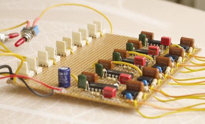
5 channels, up to 10 fans, tested & working perfectly :attn:

nice build !

As you still have plenty of space on the circuit board, you should think about adding some more capacitors or replacing the single 470 µF with some bigger one.

And after that we're ready for liftoff ...
deltafans.jpg
 
Last edited:
Regarding the cap, I wasn't sure what value to use and I had a 470uF spare. What value would be ideal for the 5 channel circuit? I have a 1000uF somewhere I think.

And that's a lot of fans... :D
 
Regarding the cap, I wasn't sure what value to use and I had a 470uF spare. What value would be ideal for the 5 channel circuit? I have a 1000uF somewhere I think.

And that's a lot of fans... :D

these are my new toys, an AFB1212SH PWM and 31 AUB0912VH.

To stabilize the 12 V rail, simply follow the good old guideline for power supplies (1000 µF for 1 Amp)
 
Back