-
Welcome to Overclockers Forums! Join us to reply in threads, receive reduced ads, and to customize your site experience!
You are using an out of date browser. It may not display this or other websites correctly.
You should upgrade or use an alternative browser.
You should upgrade or use an alternative browser.
FEATURED Building PWM Controller for 4 wires PWM fan
- Thread starter Brutal-Force
- Start date
- Joined
- Jan 7, 2014
- Location
- Munich, Germany
Oh I thought you meant the 5v circuit. I don't see any reason to stabilize the 12v rail because the fans should do that already themselves!
I wonder how a fan can do that.
Even a 22 µF SMT capacitor needs more room than a fan PCB offers (at least those which I've seen).
Of course, it will work fine, but the difference on the 12V rail is measurable even with a cheap DMM.
It's also a good idea to stabilize the 5V, but not a must.
- Joined
- Nov 29, 2010
So folks, here's an update for you.
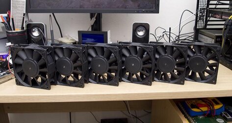
Yesterday I received 6x PFC1212DE (8-pole, 3.24A version, measured 1.99A @ 100% with DMM)
Tach doesn't work and the fans have a very strange revving behaviour and an equally strange PWM behaviour. From 0-20% fans don't spin at all, and lowest speed seems to be around 1500-2000rpm at 20%, and speed seems to go up in steps. VERY NICE sound profile though. No idea where the 3.24A rating comes from!
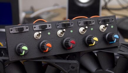
And a sneak preview of my new 5 channel 0-100% controller.


Yesterday I received 6x PFC1212DE (8-pole, 3.24A version, measured 1.99A @ 100% with DMM)

Tach doesn't work and the fans have a very strange revving behaviour and an equally strange PWM behaviour. From 0-20% fans don't spin at all, and lowest speed seems to be around 1500-2000rpm at 20%, and speed seems to go up in steps. VERY NICE sound profile though. No idea where the 3.24A rating comes from!
And a sneak preview of my new 5 channel 0-100% controller.
- Joined
- Sep 7, 2013

Very clean

Better than what I could ever build
- Joined
- Dec 10, 2012
- Location
- Western Canada
For all the knowledgeable designers here on the board.
I have assembled Bings 0-100% PWM controller c/w the Kickstart component. The fan I am using does not drop to "0" RPM, but does slow to perhaps 100 or so RPM. Is this perhaps the result of the fan I have?
Now that I have rebuilt the Kickstart circuitry (with correct resistors this time) I notice that the system operates opposite to that which Bing intended. When I turn on the power, the fan runs at very low RPM (the length of time is determined by the capacitor rating as shown on Bings circuit) then increases speed to that called for by the potentiometer.
This seems to hint that I have made and error - any suggestions anyone?
Also, I would like to understand how the Kickstart circuit works, and also understand why one of the NPN transistors has 2 leads running to ground - anyone want to take this on.
As a newcomer to electronics, I am simply trying to learn.
Hi,
Ive been lurking on this forums for quite a while and was interested to build a PWM controller but will be used for pump (MCP35X2 to be specific). Also I'd like to connect it on the 3 pin fan controllers.
Will this circuit work to control the pump with no issues?
- Joined
- Jan 7, 2014
- Location
- Munich, Germany
Hi,
Ive been lurking on this forums for quite a while and was interested to build a PWM controller but will be used for pump (MCP35X2 to be specific). Also I'd like to connect it on the 3 pin fan controllers.
Will this circuit work to control the pump with no issues?
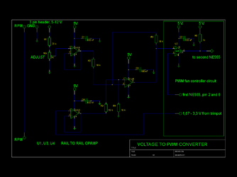
This circuit only extends Bings controller.
If you want to control the pumps duty cycle manually, you don't need this because the NE555 circuit already gives you the whole range from zero to 100%.
Anyway, it will work.
The voltage coming from the 3-pin header is inverted and then added to the reference voltage from the main circuit trimpots wiper.
The voltage level at the trimpot P1 wiper needs to be adjusted to 1,67 V.
Resistor R1 should be 20kOhm.
The opamps should be low voltage rail-to-rail types.
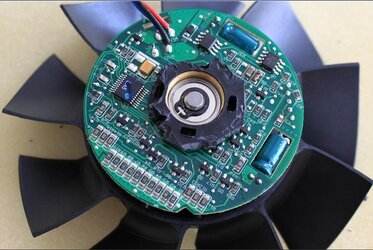
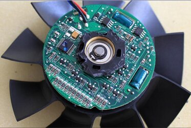
wow, that's a huge circuit board !
It's a high current fan, so I assume the capacitors are there to decouple the MOSFET stages that drive the coils.
This is the other side of the PCB.
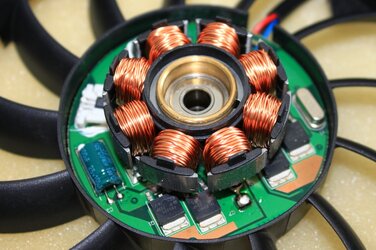
To make the supply voltage smooth, you would still need some 4000 µF.
So folks, here's an update for you.
Yesterday I received 6x PFC1212DE (8-pole, 3.24A version, measured 1.99A @ 100% with DMM)
Tach doesn't work and the fans have a very strange revving behaviour and an equally strange PWM behaviour. From 0-20% fans don't spin at all, and lowest speed seems to be around 1500-2000rpm at 20%, and speed seems to go up in steps. VERY NICE sound profile though. No idea where the 3.24A rating comes from!
some fans have a locked rotor sensor output at pin 3.
Here's the datasheet
http://helpinhand.de/media/PFC1212DE-F00.pdf
Looks like you have some OEM version with locked rotor sensor.
Some weeks ago, I bought a QFR1212EHE. It was FSC OEM, had a startup delay, PWM and "only" 3000 rpm instead of 6000 like the regular model (non-PWM).
The current value on the label is the peak current at startup.
Last edited:
- Joined
- Nov 29, 2010
For all the knowledgeable designers here on the board.
I have assembled Bings 0-100% PWM controller c/w the Kickstart component. The fan I am using does not drop to "0" RPM, but does slow to perhaps 100 or so RPM. Is this perhaps the result of the fan I have?
Now that I have rebuilt the Kickstart circuitry (with correct resistors this time) I notice that the system operates opposite to that which Bing intended. When I turn on the power, the fan runs at very low RPM (the length of time is determined by the capacitor rating as shown on Bings circuit) then increases speed to that called for by the potentiometer.
This seems to hint that I have made and error - any suggestions anyone?
Also, I would like to understand how the Kickstart circuit works, and also understand why one of the NPN transistors has 2 leads running to ground - anyone want to take this on.
As a newcomer to electronics, I am simply trying to learn.
C'mon guys, help him out
 Also if you could share a picture of your circuit with kick-start that would help with answering your questions.
Regarding the fan's PWM behaviour, every fan is different depending on how the manufacturer programmed it. I have two Nidec TA450DC which have a different "low" speed at 0% duty cycle, and my most recent fans don't even start spinning until 20% duty cycle.
@ gabomuc, thanks for the explanation. It is a big circuit board, huh?! These fans are just extraordinary.
Regarding my PFC1212DE, it's REV.00 which I can't find a datasheet for, and I think the date is 2007 so this is quite an old fan design. Like you say, this fan also has startup delay. I really like it, but I wish it had a lower speed at 0%!
There are at least 4 versions of the PFC1212DE that I can find:
8-poles, 3.24A (REV.00)
8-poles, 3.24A (REV.09 - pictures here)
8-poles, 4.8A (REV.??, has -T8SH suffix)
12-poles, 4.8A (REV.??, has -6A50 or -6C1M suffix)
FANS ARE AWESOME!
- Joined
- Apr 4, 2011
sorry,
been busy refurbishing a couple of LCD monitor given by friends of mine.
It really surprised me by how easy to repair them, just replace some of the capacitors and they're good to go
seem to me that your fan is on the inverted side, while your controller is on the non-inverted side.
or the vice versa.
anyhow the solution's quite simple.
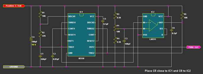
take a look at the schematic:
just swap the connection from "pin #2" to "pin #3" on the LM311.
or you can simply add another "inverted schmitt trigger" on your current controller.
been busy refurbishing a couple of LCD monitor given by friends of mine.
It really surprised me by how easy to repair them, just replace some of the capacitors and they're good to go
For all the knowledgeable designers here on the board.
I have assembled Bings 0-100% PWM controller c/w the Kickstart component. The fan I am using does not drop to "0" RPM, but does slow to perhaps 100 or so RPM. Is this perhaps the result of the fan I have?
Now that I have rebuilt the Kickstart circuitry (with correct resistors this time) I notice that the system operates opposite to that which Bing intended. When I turn on the power, the fan runs at very low RPM (the length of time is determined by the capacitor rating as shown on Bings circuit) then increases speed to that called for by the potentiometer.
This seems to hint that I have made and error - any suggestions anyone?
Also, I would like to understand how the Kickstart circuit works, and also understand why one of the NPN transistors has 2 leads running to ground - anyone want to take this on.
As a newcomer to electronics, I am simply trying to learn.
seem to me that your fan is on the inverted side, while your controller is on the non-inverted side.
or the vice versa.
anyhow the solution's quite simple.
take a look at the schematic:
just swap the connection from "pin #2" to "pin #3" on the LM311.
or you can simply add another "inverted schmitt trigger" on your current controller.
- Joined
- Dec 10, 2012
- Location
- Western Canada
Thank you invain. swapping the connections between pin#2 and #3 on the LM311 worked. The fan is still not dropping to 0 RPM, BUT, I do get the full speed kick start as the design intended.
Nice!!
The circuit I have built is the 0-100% illustrated on posting #25 by Bing. Regardless, the rewiring you suggested worked. Do you think I would have achieved the same result if I had exchanged the in/out connections on the potentiometer?
Now that I know this circuitry works, I am hoping someone on this board is making or interested in making a PC board. I have a use for this control circuit but only if I can make a permanent board.
Finally for this post, does this circuit lend itself to scaling up to a large 12VDC motor?
- Joined
- Dec 10, 2012
- Location
- Western Canada
Lenny, here is a couple of pictures of my project. I am happy to say the circuit is working well. The circuit at the left of the picture is a 12 & 5 VDC power supply I could elsewhere at the "Internet Engineering Design Company".
The only variance I can detect between the description of 0 - 100% circuit and mine is that with my build the fan does not drop to 0%. This is no problem for me.
Hmmm seems I am unable to attach my pictures. . . . suggestions?
The only variance I can detect between the description of 0 - 100% circuit and mine is that with my build the fan does not drop to 0%. This is no problem for me.
Hmmm seems I am unable to attach my pictures. . . . suggestions?
- Joined
- Sep 7, 2013
Lenny, here is a couple of pictures of my project. I am happy to say the circuit is working well. The circuit at the left of the picture is a 12 & 5 VDC power supply I could elsewhere at the "Internet Engineering Design Company".
The only variance I can detect between the description of 0 - 100% circuit and mine is that with my build the fan does not drop to 0%. This is no problem for me.
Hmmm seems I am unable to attach my pictures. . . . suggestions?
EarhtDog's favourite pic

- Joined
- Dec 10, 2012
- Location
- Western Canada
Ok Thanks Silver Pharaoh. Always great to get advice from knowledgeable folks.
Let's see if this works.
Let's see if this works.
- Joined
- Dec 10, 2012
- Location
- Western Canada
Well I'll be darned!!!
- Joined
- Apr 4, 2011
@sandrat,
that breadboard is such a beast....
something that'd do only on my audio research (p.s just because I would, it doesn't mean I'm doin' it
 )
)
great looking setup
as for the permanent pcb,
let's wait for Bobnove appear on our classie.
I build a pcb for myself, but unfortunately sending them out abroad is out of question
but, you can always made your controller on a perfboard like Lenny did.
yes, I do think something similar with yours.
I'm really curious to add a variable resistor in series with "R3" and "R4".
let's say a 1k vr, and swap the R3 and R4 value to 8.2k,
and see if we can have a better performance on the low side of the fan rpm.
but first, I need to dig out on of my 9SG out of the case
@Lenny,
since you ever brought the rotary switch issue to this forum, I began to think;
why not use a rotary switch to switch between a fan rpm sensor that'll feed to a mobo rpm sensor header.
ofcourse, you can use them to feed the signal to your Alphacool screen.....
man, I do envy you
that breadboard is such a beast....
something that'd do only on my audio research (p.s just because I would, it doesn't mean I'm doin' it

great looking setup

as for the permanent pcb,
let's wait for Bobnove appear on our classie.
I build a pcb for myself, but unfortunately sending them out abroad is out of question

but, you can always made your controller on a perfboard like Lenny did.
yes, I do think something similar with yours.
I'm really curious to add a variable resistor in series with "R3" and "R4".
let's say a 1k vr, and swap the R3 and R4 value to 8.2k,
and see if we can have a better performance on the low side of the fan rpm.
but first, I need to dig out on of my 9SG out of the case
@Lenny,
since you ever brought the rotary switch issue to this forum, I began to think;
why not use a rotary switch to switch between a fan rpm sensor that'll feed to a mobo rpm sensor header.
ofcourse, you can use them to feed the signal to your Alphacool screen.....
man, I do envy you
- Joined
- Nov 29, 2010
inVain, AWESOME idea with fan rpm sensing on rotary switch. My alphacool software only allows for one fan header to report RPM which is really annoying, but the rotary switch would solve that problem, up to 12 fans!
Tomorrow I'm going to make a video of my completed 5-channel controller with 5x PFC1212DE connected (well...with 10 outputs I could connect 10, but that's just silly ). I wonder if the 12v supply wire and molex pin can handle 10 amps...
 we will see. Today I tested at 5 amps and it was totally fine.
Tomorrow I'm going to make a video of my completed 5-channel controller with 5x PFC1212DE connected (well...with 10 outputs I could connect 10, but that's just silly

- Joined
- Dec 10, 2012
- Location
- Western Canada
Thanks inVain, When I was planning to make the project I wanted to be able to follow each and every line from start to finish. So I spend some time laying all the components just so. Oh, and I also bought a magnifying glass.
I have application for this package in equipment other than a computer tower, so a PCB complete with a power supply is the next step, so hello bobnova!
I like the circuit modifications you mentioned, and the next time I get to the store I'll pick up the parts and experiment.
I have application for this package in equipment other than a computer tower, so a PCB complete with a power supply is the next step, so hello bobnova!
I like the circuit modifications you mentioned, and the next time I get to the store I'll pick up the parts and experiment.
Similar threads
- Replies
- 4
- Views
- 2K
- Replies
- 6
- Views
- 1K
- Replies
- 32
- Views
- 20K
