• Welcome to Overclockers Forums! Join us to reply in threads, receive reduced ads, and to customize your site experience!

DIY CPU Waterblock (pics inside, 56k warning) and results!

Overclockers is supported by our readers. When you click a link to make a purchase, we may earn a commission. Learn More.
I bet it'd be another degree or two cooler if you had some pure aluminum, alloying elements decrease conduction rather quickly.
Or pure copper..... omnomnomwhat?


Anyway, that is very very cool.


One thing i am wondering about, why put one hose in the middle and another on the corner, rather then forcing the water to flow from corner to corner or somesuch?
 
One thing i am wondering about, why put one hose in the middle and another on the corner, rather then forcing the water to flow from corner to corner or somesuch?
Simple, the center of the CPU (where the actual CPU die is) is the hottest part, and thus needs the best cooling. By making my inlet at the center I can cool this are very quickly since water can cool that are quickly and go to the outlet. The center is milled in a way that 60% of the water quickly goes to the outlet while the rest of the water is used to cool the rest of the cooler area of the CPU heatspreader.

I bet it'd be another degree or two cooler if you had some pure aluminum, alloying elements decrease conduction rather quickly.
Or pure copper..... omnomnomwhat?
Original design was suppose to be on Copper C110 but CNC cost put Copper out of the running. :(
 
New pics and results!

3848720607_868ce69942_o.png

Maxes out at 50C in ~3minutes of P95. It stays there for the rest of the run (~30 minutes).

3848724471_40752814da_b.jpg


3848728449_55bc0f8159_b.jpg

Quick & dirty DIY mounting. lol. Still designing actual bracket on CAD. It's not that great. Only 2 screws and not enough pressure on the block.
 
Last edited:
Little update: Ordered a bracket kit. It' will need some modding and it should arrive in about 6-7 days (Newegg Eggsaver shipping is SLOW :lol: )
 
So after getting some reinforced Dremel disks (took most of the time, bought it online due to price) and cutting it up and installing:
3896093839_4cc02579f8_b.jpg


3896875370_15191097fb_b.jpg


Setting up testing:
3896876030_61313356ed_o.png

Voltage set at 1.47 to give a more accurate comparison to the GTZ/GTX/EK
 
Why did you use a transmission radiator?
1. It was only $20 for it.

2. I needed an Aluminum rad. Most others rads were Copper tubing.

3. It works quite well with a good high CFM fan. (Using Scythe Slipstream 110 CFM fan )

Going to go P95 testing soon :D
 
Result time folks! :D

Specs:
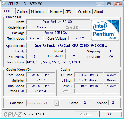
E2180 3.2Ghz @1.47v (CPUZ reading)
P35-DS3L
1x 120mm Scythe 110CFM on the heatercore/rad
120GPH ViaAqua pump.


3913334470_28b7c03fe9_b.jpg

Maxes out at at ~10 minutes of P95. 60C stays there for the next 3hrs. This is the #5 test. Will average out all and post graph later.
 
I'd say this is quite close to the GTX assuming these are accurate/comparable: http://www.swiftnets.com/products/APOGEE-gtz.asp when compairing to a E6600 3Ghz @1.47v.
I'd say it's a bit better than the Storm or the GT. Ambient temp was ~24C (75F reading) around the rad as measured from a digital thermometer. So we get a rise of 36C over ambient. Main limitation right now is the pump. The way the rad is placed, the pump dosn't have enough head. Probably will pick up a 526GPH ViaAqua (actual is ~300-350GPH from personal experience) in a few weeks (see: http://cgi.ebay.com/Via-Aqua-306-Aq...in_0?hash=item45edd76598&_trksid=p4999.c0.m14 ). I have no intention of getting a good MCP655/D5 for this project lol. I plan to do a rev 2 of this block during December.

I designed this block to be comparable and to be low cost. This block can easily be manufactured via forging/casting, (which are quite ideal than CNC for high volume production)etc. due to the size of the pins (I'm not using some insane pin pattern and sizes so yeah).
 
Back