• Welcome to Overclockers Forums! Join us to reply in threads, receive reduced ads, and to customize your site experience!

Proper droopmod for IC7MAX3 pics inside

Overclockers is supported by our readers. When you click a link to make a purchase, we may earn a commission. Learn More.
Hi again! :) I'll try to answer all of yr questions as well as I can.

First of all yr last remark about circuit droop, yes you are right, that's a typo.

The specsheets give the VID pin info. This is a voltage value that is used for the CPU to comunicate with the PWM controller chip. When you select a voltage in bios, the PWM controller implements this voltage, and sets the tension on a number of CPU pins. As far as I understand it, the proc looks at these voltages, and sends a pwgd signal, pulling one of the pwm controller pins to high, telling the pwm chip that it has accepted the voltage layout. If the pwm chip receives low voltage on this pin, it means power-no-good, and it switches the Vcore supply off.

The whole VID pin layout and the values, are not of any direct relation with the actual Vcore supplied accross the Vcc and Vss pins of the proc. I think you have to see the VID values as control values between cpu and pwm controller, nothing else. Their tolerance range lays outside that of the VRD loadline tolerance.

What I cannot oversee from here is how many Amps yr EE proc pulls under load, and this whole story is just about that (droop= loss of tension (V) due to resistance in the conductor at high current (A). These values, in our case, always lay outside of the design specs of pwm unit and cpu, since we OC the s**t out of them. So even if everything is designed to have droop under control at say 70A pwm output, when we get to +50 FSB, the whole picture is distorted, and we'r pulling in excess of 95 - 100 Amps.

This is why the best way to come to grips with the Vcore situation, (especially on socket 478 / Prescott > 3.0), is to get a proper testpoint, and observe what is actually going on.

The software measurements, have some inaccuracy, in the range of 0.02 - 0.04 V, just enough to make them useless.

Reality is that when you'r doing a high OC on thse CPU's, the window of good Vcore values, is smaller the higher you get. What I mean is that when at stock speeds, any Vcore between (Prescott) say 1.40V and 1.55V will allow the chip to run well and stable. Now, as FSB rises, this window narrows to a point where it has to lay between say for example (like my cpu at 255FSB) 1.527 and 1.519 Volts. Any value outside of this will cause instability. At 250 FSB the window is between 1.490 and 1.535 Volts.

To get you to see all this in perspective, I'd abandon all the Intel theories and specs, since we work outside of their spec anyways, and quite a bit so. Let's go by our own findings, they lead to higher OC's!!


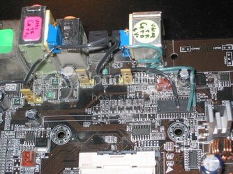


:clap:
 
Hey woutertal,

Getting down to planning this mod out. My question is, I like to swap processors in and out of my board (2.4c, SL7E5, SL7B8, etc.). What'll happen to the settings/vcore when I switch out, especially going from prescott to northwood? Should I incorporate a switch into the mod, so that I can just flip it off? Or just reset all the cermets before each switch?

2nd question. Not an electronics experts and none of the local stores have appropriate components. Would these be the appropriate pots:

20K pot: Digikey# 3296Z-203-ND
500K pot: Digikey# 3296Z-504-ND

Thanks!
navig
 
Last edited:
After spending a day following my vcore with a multimeter, I realized this: you can calculate your processor load by how much the vcore is drooping. Need to get this mod done.
 
Navig I checked those part nos, they are perfect for the job. Good luck with it!
 
Navig said:
Hey woutertal,

Getting down to planning this mod out. My question is, I like to swap processors in and out of my board (2.4c, SL7E5, SL7B8, etc.). What'll happen to the settings/vcore when I switch out, especially going from prescott to northwood? Should I incorporate a switch into the mod, so that I can just flip it off? Or just reset all the cermets before each switch?

2nd question. Not an electronics experts and none of the local stores have appropriate components. Would these be the appropriate pots:

20K pot: Digikey# 3296Z-203-ND
500K pot: Digikey# 3296Z-504-ND

Thanks!
navig

Well, if you think about it, the best way is to reset the pots to max resistance which equals an unmodded board, before you swap processor. You will want to use to mod for any processor you have, it just gives you a lot more control over your Vcore. So a switch seems unnecessary.
 
Thanks woutertal! At first I was a little apprehensive about soldering to the legs of the control chip, but after doing it multiple times to the similarly sized chips on my 9800 pro, I feel confident--but I'll take any amount of good luck also. Digikey order is in.

navig
 
Navig said:
Thanks woutertal! At first I was a little apprehensive about soldering to the legs of the control chip, but after doing it multiple times to the similarly sized chips on my 9800 pro, I feel confident--but I'll take any amount of good luck also. Digikey order is in.

navig

Navig just take it very slowly, think twice and than act. Work under a magnifying glass. That's the trick. Exercise on some old pcb you have untill you feel confident. The clue is in the size of the drop of solder you put on the wire. When it's right, the solder flows and it's ok.
 
I just updated the guide. No changes, but some more explanation as to what happens whilst adjusting.
 
woutertal, do you mind running some numbers thru with me before I install this puppy tomorrow?

My first goal is to completely stabilize my SL7E5 @ FSB 245. To be mostly stable @ FSB 245, in the bios I set to 1.5375V.
In the bios, my DMM reads 1.519V.
In windows, during idle, my DMM reads 1.549V.
Under 100% load, my DMM reads 1.493V.

I plan to install the mod tomorrow..

I can get into the bios at as low as 1.4625V. For my first boot, do I boot into bios with 1.4625V? Then what do I adjust the Vofs to? Should I be measuring with the DMM or going by what the bios reads?

Should I be shooting for a reasonable voltage, say 1.510V in windows idle with a .04V droop under load? And by droop do you mean what is set in the bios minus what is read by the DMM under load, or by DMM windows idle minus DMM under load?

Any help is greatly appreciated!
navig
 
Navig, from your figures, 1.4625 seems to be a good startppoint as bios setting.

Before you install, note which way to turn the cermets for increase and decrease of resistance.

When you boot first time, have yr dmm connected. The only danger is too high Vcore, anything else is ok. If too high, immediately switch off. Decrease resistance on Vofs and try again. If too low, yr rig wont post, but you can adjust the Vcore untill it's good, and than reboot.

Now decrease resistance on Vdroop, and whislt you do that, droop decreases (you don't see this, but it happens) and Vcore rises. Adjust untill you get to say. 1.59V, and than readjust Vofs down to 1.42 or something, and son on. In between adjustments, boot into windows, and measure droop. Carry on adjusting untill your droop is what you want tit to be. I now use 0.02V as droop :).

You can fine tune Vcore on the fly anytime with the Vdroop cermet.
 
circuit1.jpg

Okay, got the circuit up and running. I did drop some solder bridging legs 12 and 13, but it picked up easily. My advice is this: isolate the goal leg by masking off the rest with electrical tape.

After a fair number of adjusting and reboots, I've got my droop down to 0.018V, allowing 4ghz FSB 250 stable for 3dmark01se.

Thanks woutertal!

After some consideration, I'm not sure what the point of having load droop is, so I'm headed to zero droop.

navig
 
Last edited:
Wow, woutertal, this is actually changing how I overclock!

Things to keep track on a piece of paper: the minimum voltage it takes to just enter windows for a give FSB. That way, when you are trying to decrease you're droop, you know what voltage to adjust your Vofs to in the bios. Then you hit up windows, and increase the Vcore as high as you can go by adjusting Vdroop. Increasing the core decreases Vdroop. Reboot to bios, adjust Vofs back to that minimum voltage, hit up windows. And so on and son, until your Vdroop is as small as you like.

Once set on a Vdroop and a FSB, then you can go about minimizing your voltages. I load my processor with P95 and adjust the voltage downwards on the fly until it errors out. Add back some voltage, stop P95 and take note of your idle Vcore. Voila, minimum stable voltage.

I'm working on stabilizing FSB 240 because I'm finding this allows me to set my fans to minimum rpms and maintain temps of 55c. Before this mod, I had to set the bios to 1.5125V to maintain stability. Now I've got it down to somewhere around 1.430V idle with a 0.006V droop. That's a huge difference idling 1.5125V vs 1.430V!

navig
 
Hey Navig, Congrats! Your soldering work looks excellent. :clap: :clap:

I'm happy it helps yr OC. It is true that, once you grab very precise control over yr Vcore with this mod, the whole game changes, as you describe.
 
I know that this is the abit forum, but couldnt this type of "fix" be applied to the asus p4c800 series boards, they seem to have the same controler, and the whole soldering would be way easier than the janky way you have to go about it now... But, i could be wrong...... :confused:
 
screwtech02 said:
I know that this is the abit forum, but couldnt this type of "fix" be applied to the asus p4c800 series boards, they seem to have the same controler, and the whole soldering would be way easier than the janky way you have to go about it now... But, i could be wrong...... :confused:


I have received loads of questions similar to this one. The answer is that yes, indeed, if you locate this ISL6554BCB controller chip on any mobo, you can basically just perform this mod as described.

However, I have not tested this on other boards, and it is probable that the initial resistance settings of the cermets will have to be different. The best way to do it is to set them to maximum resistance, and work your way down.

But I thought that the Asus boards had the ADP3180 controller?
 
Last edited:
Acck! It does have a adp controler, is that going to be a Major difference?? I just noticed that the chips looked similar in layout, and figured that it would be easier to solder to the controler legs... :-/
 
screwtech02 said:
Acck! It does have a adp controler, is that going to be a Major difference?? I just noticed that the chips looked similar in layout, and figured that it would be easier to solder to the controler legs... :-/

I'd insist that it easier to solder to the points as the original Asus droopmod :D
 
Excellent! This is exactly what I'm looking for. I'm going to try it on my IS7, same ISL controller chip:) Right now I set the vcore at the max 1.525v in BIOS but actual value in PC health monitor only shows 1.42v~1.44v. I just don't believe it is because of my 350w power supply, which can supply 16A on 12v line, that's 192Ws, plenty enough for even the most power hungry prescott.
 
I wonder if there is a 0.4v droop between the "real" vcore(blue wire in the pic) and BIOS vcore(legs of the chokes) because of the insufficient gauge and the intel designed droop, wouldn't the simplest mod be just solder a big thick wire between them therefore "bypassing" the designed droop?
 
Back