• Welcome to Overclockers Forums! Join us to reply in threads, receive reduced ads, and to customize your site experience!

FEATURED Brass Tacks: One Day Scratch Build

Overclockers is supported by our readers. When you click a link to make a purchase, we may earn a commission. Learn More.

Navig

Senior Case Master
Joined
Dec 7, 2003
Brass Tacks: One Day Scratch Build

In colloquial English, Brass tacks (often "get down to brass tacks") refers to the fundamental or essential elements of a topic.
(wikipedia)


I’m putting together my next scratch build, and I am going to attempt to build it in one single day.
Its going to be pretty basic build, with minimal finish. The base framework is based on my exoframe, but I’m going to simplify the plastic paneling by just flush-mounting it instead of inset mounting them.

I’m planning for Monday or Tuesday.

But the next few posts, I’m going to lay out all my planning.


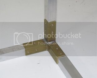
First of all, a single day may be a little ambitious, but I am starting with my DIY corner brackets already pre-made.


Finishedbracket1.jpg


DIY Inside corner bracket thread.


If you read thru the post,

1) This is the project I was referring to when I first put the brackets together

2) I also mention that while you could easily powdercoat the brackets, I was going to leave them unfinished brass for this project.


That is why I’m titling this project Brass Tacks: I’m going to be using a lot of unfinished/raw brass and metal as part of this build to simplify the look and make it possible to complete in one day (hopefully).


.
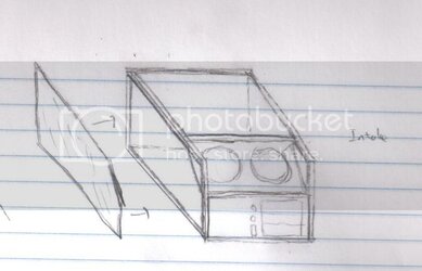
 
And here is my design process:


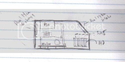
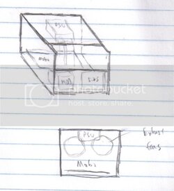
First I started with some general sketches.


Plan1.jpg


Plan2.jpg


Plan3.jpg


Comments: You may notice this a pretty familiar general design as my previous projects (Exoframe and Exoframe 2), altho this one is actually not going to be technically an “exoframe” as the plastic paneling will be surface mounted instead of inset.


The layout is going to be definitely different from previous designs. I’m going to put my large intake fans (14cm) on the front sloping panel, and the PSU is going to hang high, dropping down its cables to the motherboard, which will be mounted to the bottom panel.
 
Specific Inventory

Here’s a list of raw materials I’ve assembled for this project (plus I’ve got many usual type items around my shop).

Brass Inside Corner Brackets, 4
Aluminum end caps, 6
Aluminum square tube stock ¾” x 1/16” wall thickness
Brass L brackets 1.5”, 4
Brass L brackets 2.5”, 4
Brass 90 degree angle brackets, 4
Brass angle stock ¾” x 1/16” thickness
Brass strip stock ½” x 1/16” thickness

Plastic stock
⅛” clear sheet 2’x4’ sheets, 2
¼” clear sheet 742mm x 610mm

Brass pulls (for feet), 4
Brass momentary switches, 2
Brass cable clips symmetric ⅜” hole, 8
Brass cable clips “J” ¾” hole, 10

1” hex standoffs, 10

PCI bracket, black anodized

PSU bracket black anodized

3x5.25 bay, silver brushed

Hard drive rack unit

Brass threaded rod 1’, 2

Corrugated split cable conduit ⅝”, 5’
Corrugated split calbe conduit ⅞”, 5’

GVans fan controller

USB front cable

Sata power and data cables

Brass 6-32 pan head screws, ⅜” and ¼”
 
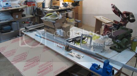
Here is a photo of all the stuff for this project. It’s really hard for me to not jump in and just start tinkering right now, but I feel like it’ll be an interesting exercise to do it in one day.

Inventory1.jpg


Next step: layout my build plan.
 
Master Pre-Plan

1) Cut the square tube:

Cut List:

Square to 45 degree: (longest length):
351mm, #2
641mm, #2

Square to Square:
422mm, #4
456.8mm, #3
332mm, #2
622mm, #2


2) Assemble frame (tap and thread)
Square tube
Corner brackets
90 angle brackets
L brackets

3) Cut sheet plastic stock (size to be determined):
Front (#1) ____ mm x ____ mm
Sides (#2, #4) ____ mm x ____ mm
Top (#3) ____ mm x ____ mm
Bottom (#5) ____ mm x ____ mm
Back (#6) ____ mm x ____ mm
Slant panel (#7) to be worked on later

4) Start on Bottom panel (#5)
Notch corners
Cut shim brass pieces (1/2” trim)
Mount shim brass trim
Mount Bottom panel (#5)

5) Locate and place motherboard mounts on Panel #5

6) Mount Back Panel #6
Locate PCI rack on Back Panel #6
Cut out hole for PCI and i/o rack.
Mount PCI bracket
Cut fan holes

7) Start work on Slant Panel (#7)
Cut rectangle, with beveled edges
Cut out notches, with beveled edges
Fabricate mounting brackets
Mount Slant Panel (#7)
Cut fan holes

8) Complete slanted corners on Side Panels #2 and #4

9) Work on PSU mount
? Threaded rod and brass angle bracket
? Back panel (#6) thru hole

10) Finish work for Front Panel (#1)
Cute 5.25 bays hole
Mount 5.25 bay
Mount brass momentary switches
? Figure out LED indicators and mount
Cut holes and mount USB front panel

11) Mount Hard Drive Rack to Bottom Panel (#5)

12) Mount cables and route

1) PSU: 24 pin
8 pin
Supply to 5.25
Supply to hard drives
GPU cables
2) 5.25: interface to PSU
Data cables
3) Hard drives: interface to PSU
Data cables

13) Install PC hardware

14) Plan out split corrugated conduit

? paint conduit

15) Done!
 
Planned Date:

Tuesday, August 8, 2012!
 
Whew, that's quite the list for one day; looking forward to seeing this one come together.

Do you have a web cam? You could livestream it. :D
 
Sorry, alas I do not. I plan on posting a quick pic and time at each step I accomplish.

See y'all in the morning.
 
Step Zero

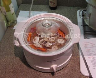
Potroast.jpg

Pot roast in the slow cooker.


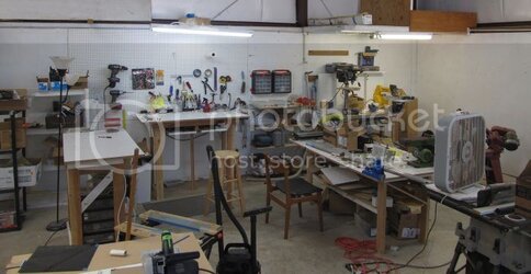
And the shop is open for business:

Shopisopen.jpg


0851 PST
 
1) Cut the square tube:

Cut List:

Square to 45 degree: (longest length):
351mm, #2
641mm, #2

Square to Square:
422mm, #4
456.8mm, #3
332mm, #2
622mm, #2


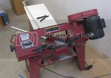
Cut on my bandsaw:


Bandsaw.jpg


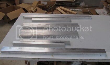
Stock cutting is done:


Stocksquaretube.jpg


0945 PST
 
2) Assemble frame (tap and thread)
Square tube
Corner brackets
90 angle brackets
L brackets


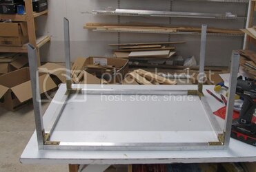
Definitely running behind, but the frame is coming together:


Frameiscomingtogether.jpg


Like to get the frame together before lunch, but I'm not sure.

Its already getting hot here in Chico, CA.

1142 PST.
 
Back