-
Welcome to Overclockers Forums! Join us to reply in threads, receive reduced ads, and to customize your site experience!
You are using an out of date browser. It may not display this or other websites correctly.
You should upgrade or use an alternative browser.
You should upgrade or use an alternative browser.
I'm thirsty for electricty
- Thread starter Tay
- Start date
OP
- Joined
- Jan 18, 2005
- Thread Starter
- #2
Found this: http://www.ocforums.com/showthread.php?t=347434. Kinda hard for me to understand tho.
To put it simply, you need to solder a 50K OHm VR to a ground, and to pin 7 of the HIP6302 voltage regulation IC on your motherboard. You can get the 50K Ohm VR you need, HERE.
Before you start, set the Vcore voltage as low as you can through your motherboard's BIOS. Doing this will prevent you from overvolting too much to begin with, which could damage your processor.
Step-by-step:
1. Solder a long, thin wire (single strand IDE cable wiring works really well) to one of the outside legs of your 50K Ohm variable resistor.
2. Solder another long, thin wire to the center leg of your 50K Ohm Variable resistor.
3. Break off the third, unused, outside leg on your 50K Ohm Variable resistor.
4. Set your 50K Ohm VR to 50K Ohms of resistance, check it using a multimeter, measuring resistance across the two wires which you have soldered onto the VR.
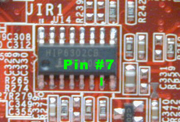
5. Solder the wire on the outside leg of your 50K Ohm VR to pin #7 of the HIP6302 IC. Pin 7 is shown in the link that you posted, but I have attached a picture for you.
6. Solder the wire on the middle leg of your 50K Ohm VR to a ground. Easy grounds to use include Pin #9 of the HIP6302 IC, or any unused 3-pin motherboard fan port ground.
7. Fire up your machine. Slowly lower the resistance of your 50K Ohm VR in order to increase the Vcore overvolt. Turn the VR slowly with 1/4 turns, and moniter the Vcore overvolt through the motherboard BIOS as you adjust the VR.
Thats all there really is to it") . Optional, but highly reccomended, is a jumper soldered inline with the ground wire, to make the voltmod removeable.
. Optional, but highly reccomended, is a jumper soldered inline with the ground wire, to make the voltmod removeable.
If you are a little sketchy about soldering on your motherboard, spend some time and practice soldering leads onto a dead piece of hardware before you operate on your board.
Good luck.
Before you start, set the Vcore voltage as low as you can through your motherboard's BIOS. Doing this will prevent you from overvolting too much to begin with, which could damage your processor.
Step-by-step:
1. Solder a long, thin wire (single strand IDE cable wiring works really well) to one of the outside legs of your 50K Ohm variable resistor.
2. Solder another long, thin wire to the center leg of your 50K Ohm Variable resistor.
3. Break off the third, unused, outside leg on your 50K Ohm Variable resistor.
4. Set your 50K Ohm VR to 50K Ohms of resistance, check it using a multimeter, measuring resistance across the two wires which you have soldered onto the VR.
5. Solder the wire on the outside leg of your 50K Ohm VR to pin #7 of the HIP6302 IC. Pin 7 is shown in the link that you posted, but I have attached a picture for you.
6. Solder the wire on the middle leg of your 50K Ohm VR to a ground. Easy grounds to use include Pin #9 of the HIP6302 IC, or any unused 3-pin motherboard fan port ground.
7. Fire up your machine. Slowly lower the resistance of your 50K Ohm VR in order to increase the Vcore overvolt. Turn the VR slowly with 1/4 turns, and moniter the Vcore overvolt through the motherboard BIOS as you adjust the VR.
Thats all there really is to it
. Optional, but highly reccomended, is a jumper soldered inline with the ground wire, to make the voltmod removeable. If you are a little sketchy about soldering on your motherboard, spend some time and practice soldering leads onto a dead piece of hardware before you operate on your board.
Good luck.
Attachments
Yes, the part I linked you to is the variable resistor (a good multi turn 50K Ohm potentiometer) that you need to use for the mod. The ground on the three pin fan plug is the pin with the black wire attached to it, the far right pin, when looking at the plug from the front with the prongs pointing down .
Good luck with the mod, let us know how it goes.
.Good luck with the mod, let us know how it goes
.- Joined
- May 30, 2004
Tay said:My MSI K7N2 Delta-L only gives me 1.8, and I want more! So give me links, advice, caution, instructhins, anything!
Thanks
It's an issue that may only occur with Athlon XP 2000+s and lower class processors. When I got an Athlon XP 2400+ my motherboard then allowed me to select 1.85V. With the Athlon XP 2000+, it only allowed me to select 1.80V at the max.!
- Joined
- Apr 26, 2005
hi
im haveing a similar problem my p4v88 asrock duse not have ajustments for voltage soo i cant get much over clocking done.
can you help
im haveing a similar problem my p4v88 asrock duse not have ajustments for voltage soo i cant get much over clocking done.
can you help
You want the "Potentiometer Multiturn Side Adjust (Vertical), 25 Turn" one, in the 50K Ohm flavour .
You always want to use a multi-turn potentiometer. Multi turn variable resistors can be adjusted to a much greater degree of accuracy than single turn variable resistors - when we voltmod, very minute changes to the VR's resistance cause signifigant increases to our overvolt. A single turn potentiometer is too 'rough' for fine-tune overvolt adjustments.
.You always want to use a multi-turn potentiometer. Multi turn variable resistors can be adjusted to a much greater degree of accuracy than single turn variable resistors - when we voltmod, very minute changes to the VR's resistance cause signifigant increases to our overvolt. A single turn potentiometer is too 'rough' for fine-tune overvolt adjustments.
I can't see particularly well, the picture's a little blurry 
One thing I can see though, is that you used a really long strand of wire from the hotpoint (pin 7) to the VR and ground. Generally speaking, you want to keep your wires as short as possible - I'd re-wire it so that it takes a more direct route to your ground and VR. Other than that, if it is soldered cleanly, and everything is securely attached, you should be good to go (hot glue works great for attaching the VR to your motherboard)
That's one funky looking motherboard!
- Joined
- May 6, 2004
- Location
- I live by a Delta
I would rather see you use heatshrink on that splice instead of tape. Depending on the quality of the tape, it does have a nasty habit of unraveling or sliding over time especially when used on such small wire since it is very hard to wrap it correctly.
- Joined
- Oct 11, 2003
Actually, instead of cutting the wire, and soldering it back together, unsolder the wire where it connects to the variable resistor. Then cut it to the shortest length possible, and resolder it to the VR. That way you don't have an extra solder joint to create resistance, or to short out.
OP
- Joined
- Jan 18, 2005
- Thread Starter
- #18
Ok, wire shortened.
I don't know if the guy checked it or not, I don't think he did. Would I be alright by just plugging it in?
4. Set your 50K Ohm VR to 50K Ohms of resistance, check it using a multimeter, measuring resistance across the two wires which you have soldered onto the VR.
I don't know if the guy checked it or not, I don't think he did. Would I be alright by just plugging it in?
You really do need to check the resistance before firing it up - big peace of mind factor for safety . VRs typically come set to a 'middle' resistance, 25K OHms in this one' s case, which should be O.K. - although I would check anyways just to be sure, and as a safety precaution.
If it is set too low, your overvolt may be unreasonably high, which could damage something. It is also important to set your VCore as low as possible in the BIOS before firing it up, and for the same reason - if the overvolt is larger than expected, it won't be too much, on account of the low BIOS/hardware/stock setting.
. VRs typically come set to a 'middle' resistance, 25K OHms in this one' s case, which should be O.K. - although I would check anyways just to be sure, and as a safety precaution.If it is set too low, your overvolt may be unreasonably high, which could damage something. It is also important to set your VCore as low as possible in the BIOS before firing it up, and for the same reason - if the overvolt is larger than expected, it won't be too much, on account of the low BIOS/hardware/stock setting.
Similar threads
- Replies
- 59
- Views
- 1K