- Joined
- Aug 25, 2001
- Location
- Ontario, Canada
I've been wanting to do this for a long time. Finally got around to doing it. And good news too: I didn't blow anything up!
(click on any picture to see the full sized version)
Idea:
 =>
=>

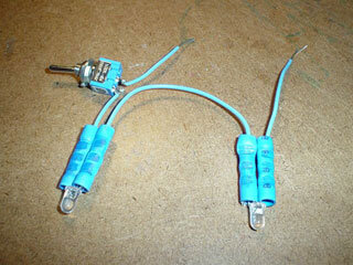
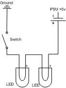
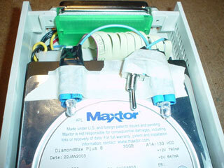
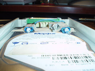
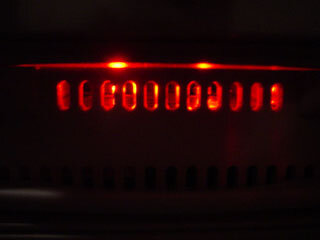
The idea is to LED-mod my removeable harddrive, with a catch. I wanted the LEDs to act like the HDD light, where they only turned on when the harddrive was busy.
So... here's how I did it:
Components Needed:

1x Removeable Harddrive, with a grill or something to let the light out
1 x Spool o' Wire
1 x Switch (optional:should you want to turn it off)
2 x 3000 MCD Red LEDs, with a 3-5v tolerance.
1 x Roll of Electrical Tape
Tools Needed:
Wire Stripper or Scissors
Soldering Iron
Solder (optional)
Knife
Magnifying Glass (optional)
My Total cost (CDN): $2.00.. (I had everything except for the LEDs.)
Here is the inside of the Harddrive Enclosure before:

First step is to remove everything. Mine allows me to remove the connector at the back for easy access to the wires.
Next, locate the correct wire on the bus. Harddrives usually ground pin #77 (or, on a 40-pin cable, #39) when they are busy... So the idea here is to give the LEDs +5, and ground them to that pin (so that when the harddrive is busy, it'll close the connection, completing the circuit.
On a 40-pin cable, it should be pin #39 (the 2nd last one). The marked end is pin #1.
On a 80-pin cable, it should be pin #77 (the third from the end). The 80-pin cable is the same as the 40-pin cable, except that there is a ground pin put between every wire. (78 would be the ground for 77, 79 would be the last pin, and 80 would be it's ground)

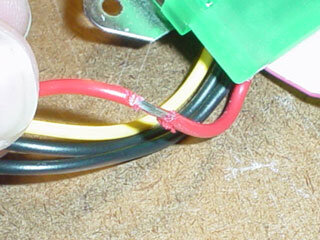
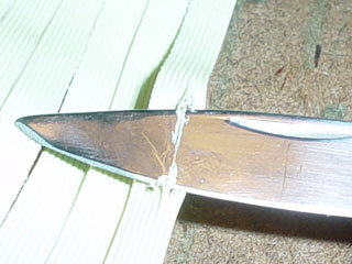
Cut it out very carefully, as not to distrub any wires around it.
(continued... more than 5? images)
(click on any picture to see the full sized version)
Idea:
 =>
=>
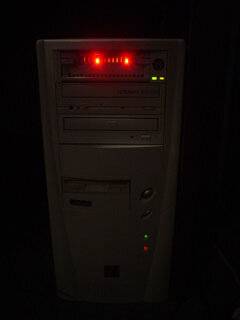
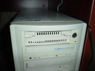
The idea is to LED-mod my removeable harddrive, with a catch. I wanted the LEDs to act like the HDD light, where they only turned on when the harddrive was busy.
So... here's how I did it:
Components Needed:
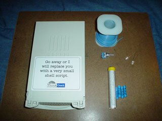
1x Removeable Harddrive, with a grill or something to let the light out
1 x Spool o' Wire
1 x Switch (optional:should you want to turn it off)
2 x 3000 MCD Red LEDs, with a 3-5v tolerance.
1 x Roll of Electrical Tape
Tools Needed:
Wire Stripper or Scissors
Soldering Iron
Solder (optional)
Knife
Magnifying Glass (optional)
My Total cost (CDN): $2.00.. (I had everything except for the LEDs.)
Here is the inside of the Harddrive Enclosure before:
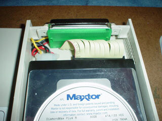
First step is to remove everything. Mine allows me to remove the connector at the back for easy access to the wires.
Next, locate the correct wire on the bus. Harddrives usually ground pin #77 (or, on a 40-pin cable, #39) when they are busy... So the idea here is to give the LEDs +5, and ground them to that pin (so that when the harddrive is busy, it'll close the connection, completing the circuit.
On a 40-pin cable, it should be pin #39 (the 2nd last one). The marked end is pin #1.
On a 80-pin cable, it should be pin #77 (the third from the end). The 80-pin cable is the same as the 40-pin cable, except that there is a ground pin put between every wire. (78 would be the ground for 77, 79 would be the last pin, and 80 would be it's ground)
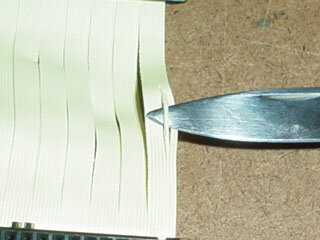
Cut it out very carefully, as not to distrub any wires around it.
(continued... more than 5? images)
