• Welcome to Overclockers Forums! Join us to reply in threads, receive reduced ads, and to customize your site experience!

FEATURED Build Log: Water & Wood

Overclockers is supported by our readers. When you click a link to make a purchase, we may earn a commission. Learn More.
Rethreading a hole is pretty easy. Since your JP, you should be able to get a 4mm tap. It's wide enough that it will make nice new threads.

Except you mention 6/32. 32 is the threads per inch. 10/24 is the usual small thread rough thread per inch. 32 is the fine pitch.

I remember reading more than once that a xx mm size works just like a 6/32. It messes the threads up a teeny bit, works fine on rads and other thin soft metals. As long as it's not something that needs redone all the time.

Since your a modder, you should look into a small tap set of metric and inches. It will help in the long run.

Love your work, your pics.
 
Looking really nice!

Is that last pump you added inverted? Is it in the same loop as the 35x, in series?
 
Yes, and yes :thup:
Ok that's what I thought. As a friendly warning: it's generally not adviseable to put the inlet "upside down" like that because you may run the pump with a bubble of air in it and that would be bad. Usually pumps need net positive suction head NPSH or basically some amount of water above the pump so the inlet is always supplied with water. Also the flow through the system could be hindered if the 35x puts out more flow than the 10w can. I think it is adviseable to put the second pump in parallel and locate it lower in your system. Sorry to be a downer man. :rain:

EDIT: I checked and the MCP350 puts out 1.9GPM max whereas the MCP35x will do 4.75GPM. If you wanted more pressure (ie stacking pumps) I'd recommend a second MCP35x in series as they are compatible in specs. Caution: in series if one pump fails it impeeds the progress of the second - in Parallel they are redundant (and can be different).
 
Last edited:
It's not a downer at all....but I disagree with everything :p Except maybe the air bubble stuff. :shrug: My thoughts on that are that because the 35X is pushing variable flow (I have its speed temp controlled by the mobo's PWM circuit to vary between 40 and 50%), and the 10W pump speed is static, any chance of an air bubble forming is really minimized. If one did form when I first hooked it up it would have been short lived me thinks, due to the varying inlet pressure. Secondly, I think I would be able to check and see if the 10W pump had an air bubble by disconnecting the 35X while in operation, in which case flow would virtually cease, right? This is something I've done, and my flow stays about the same, indicating the water is flowing correctly to the 10W pump inlet (no air bubbles), right?

Next up, parallel pumps are never a good idea. Under some circumstances, they can increase pressure quite a bit, but it never works to increase flow or redundancy effectively. If one pump fails, the failed pump's half of the circuit becomes a "short circuit" and water flows backwards through it which robs the rest of the cooling loop of a massive amount of flow. Basically, running pumps in series is the only logical choice.

Lastly, concerning the flow differences, as I mentioned before, the MCP-35X is varying its power between 40% and 50%...the 10W pump is set up with a constant 7V. I've tested each pump individually and based on the visual indicators I get from the water flow through the res, I'd guess the 10W pump is pushing approx the same amount as the 35X at 45% or so.....what does that mean for the loop? IMO, the 10W pump is a bit of a balancer, hindering flow slightly when the 35X is at 50%, and helping flow slightly when the 35X is at 40%.

But, my one an only purpose for adding the 10W pump is for redundancy, and for that purpose, I think its serving that purpose swimmingly :)
 
It's not a downer at all....but I disagree with everything :p Except maybe the air bubble stuff. :shrug: My thoughts on that are that because the 35X is pushing variable flow (I have its speed temp controlled by the mobo's PWM circuit to vary between 40 and 50%), and the 10W pump speed is static, any chance of an air bubble forming is really minimized. If one did form when I first hooked it up it would have been short lived me thinks, due to the varying inlet pressure. Secondly, I think I would be able to check and see if the 10W pump had an air bubble by disconnecting the 35X while in operation, in which case flow would virtually cease, right? This is something I've done, and my flow stays about the same, indicating the water is flowing correctly to the 10W pump inlet (no air bubbles), right?
Next up, parallel pumps are never a good idea. Under some circumstances, they can increase pressure quite a bit, but it never works to increase flow or redundancy effectively. If one pump fails, the failed pump's half of the circuit becomes a "short circuit" and water flows backwards through it which robs the rest of the cooling loop of a massive amount of flow. Basically, running pumps in series is the only logical choice.

Lastly, concerning the flow differences, as I mentioned before, the MCP-35X is varying its power between 40% and 50%...the 10W pump is set up with a constant 7V. I've tested each pump individually and based on the visual indicators I get from the water flow through the res, I'd guess the 10W pump is pushing approx the same amount as the 35X at 45% or so.....what does that mean for the loop? IMO, the 10W pump is a bit of a balancer, hindering flow slightly when the 35X is at 50%, and helping flow slightly when the 35X is at 40%.

But, my one an only purpose for adding the 10W pump is for redundancy, and for that purpose, I think its serving that purpose swimmingly :)
Hey if it works then cool - rock on! :attn:

I'm coming at this from a different angle. Back in engineering school they tell you that must have NPSH or you're doing it wrong. Not that it can't be done it just was frowned upon.

As far as the parallel verus series: I didn't know that the DDC pumps impeller would spin free enough to allow flow by when powered off. That makes a difference. All you'd need is a check valve to fix the recirculation if you did have them in parallel. That was the mistake the person in your link made. In industry parallel is used for more flow - just like two fans on a radiator side by side. Series is for more pressure like the push pull or even stacked fans. Basically the first fan or pump does the first pressure increase and the second adds from there. That's how deep well pumps work.

In your case it sounds like you have it balanced out such that the MCP35x is slowing down to match the speed of the MCP350. That makes a nice stacked pump set up that will increase the pressure because the MCP35x is making the MCP350's job easier.

Anyway, I'm not saying you are wrong just unorthodoxed in my opinion -you darn rebel! :p I just don't want that nice build to have any future problems.
 
I've always taken pride in my unorthodoxed ways :rofl:

Thanks Owenator, I do appreciate your comments :salute:
 
Parallel pumps should increase flow potential, serial should increase pressure potential. (In both cases how much of what is increased depends on the specifics of the test loop)

Serial is definitely better for redundancy, though parallel with check valves beats it.
 
Meanwhile....I'm getting impatient :mad:

jk...since the rig is up and running (and I'm happily working through Mass Effect 2), I'm in no hurry :p

But, I am looking forward to continuing when the new tools arrive :thup:
 
Sheesh, over a month without an update....whats the deal?!?

Well, I ordered some tools from Sears.com and they ship to APO addresses via USPS "Parcel Post", but fail to mention that in the shipping info. Anyhow, I just finally got my package from them, which included a new jigsaw and some router bits. Which is whats been holding up progress on this build.

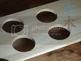
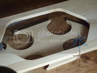
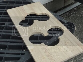
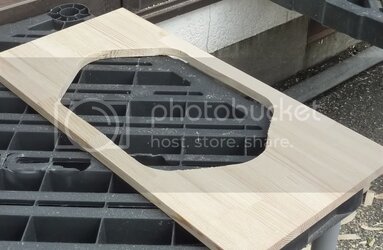
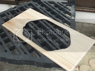
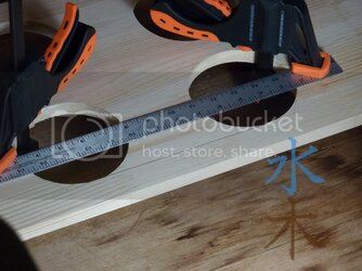
So I set to work on the front door again, cutting out the window opening to the desired shape & size. I used a ruler to guide me on the straight parts.

door32.jpg

door33.jpg

door34.jpg

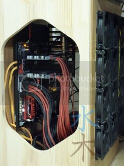
Then threw it up on the desk to make sure I was happy with the result :D

door35.jpg

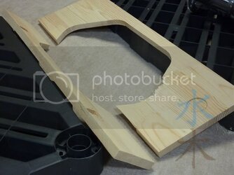
After taking it back down and removing the hinges so I could start routing it for the window and disaster struck! :shock:

door36.jpg

Anyhow, I'll have to start over with the door later :bang head

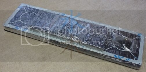
But, I also had a nice little package arrive from Portugal....

filter10.jpg

Whats this :confused:

filter11.jpg

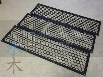
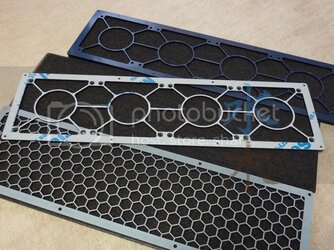
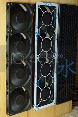
:attn:Oh yeah! My new fan grills slash dust filters :clap:

Coldzero Team saw my mod earlier and offered to send me a few things. For now, I'll just show off the filters, I'll save the other goodies for later :D

Thanks Coldzero Team!
logo-black.png


filter12.jpg

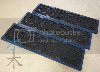
filter13.jpg

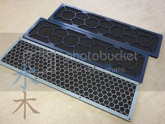
filter14.jpg

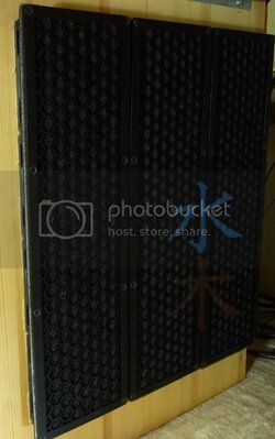
These things are amazingly nice quality. Its a two step process getting them fitted, step one you attach the bottom piece to the fans, step two is to sandwich the filter material with the top piece which screws into the bottom piece with countersunk hex head machine screws (yes, the bottom piece has been tapped for these screws to attach). Anyhow, really impressed with the quality and simplicity of the design. The shot below gives you a good idea of the process. I had to attach the lower piece with zip ties since the holes had already been drilled out as detailed earlier.

filter15.jpg

filter16.jpg

I'm headed out for a vacation next week, so my next update won't be until mid August...until then, happy modding/overclocking :D
 
Last edited:
When you get a moment TJ, I'd love to hear your input :salute:....I won't have time to try again until after my vacation, so I'll have plenty of time to digest your response :thup:
 
Well, I'm back from my vacation and back on day shift at work. Both factor in better to progress on this build ;)

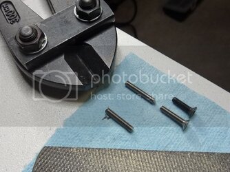
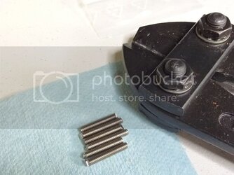
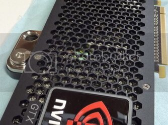
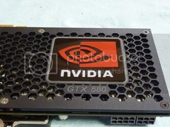
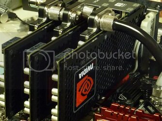
As I mentioned earlier...the kind folks over at Team ColdZero sent me some other special pieces....some beautifully crafted GTX 580 backplates. These things are gorgeous! Only one issue, two of the 6 screws they included were not long enough to get into the EK water block on the front. So I had to improvise.

backplates1.jpg

backplates2.jpg

Since these will never really be seen anyway, I was not too concerned with the aesthetics. So this should work fine, Although I could always take my sharpie to them later.
backplates3.jpg

backplates4.jpg

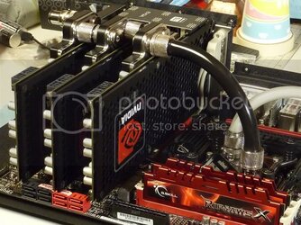
I also gave serial one more go, but these Bitspower QDC fittings are not long enough and they started leaking pretty quickly.

backplates5.jpg

backplates6.jpg

So I put the EK bridge back on and ditched the X-Fi for now....I'm in the market for a low profile PCIe card, any suggestions?

Moving on. I got another piece of wood to give the door another try.

newdoor1.jpg

newdoor2.jpg

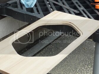
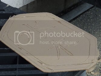
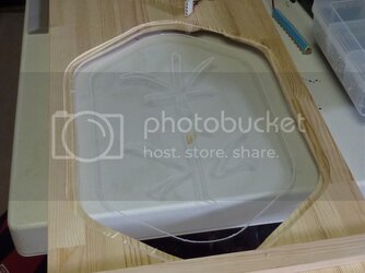
I mentioned before that this is the first thing I've ever used a router on. This is the backside of the door and I created this groove to set the window into.

newdoor3.jpg

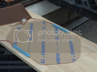
Then I had to trim the window to fit. I used my Jigsaw at a very low speed with a fine metal blade.

newdoor4.jpg

Almost there.

newdoor5.jpg

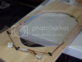
Next I had to figure out how I would position the LEDs for edge lighting.

newdoor6.jpg

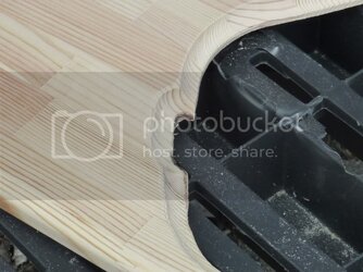
Then I tried to route the front side of the window opening and my noobiness with wood-working started showing through again :(

newdoor7.jpg

So, I decided to push ahead and see what it would look like with this messed up door, I'll have to try a 3rd time later.

newdoor8.jpg

newdoor9.jpg

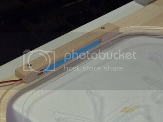
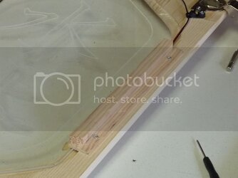
Next I had to figure out a way to hold the LEDs in position.

newdoor10.jpg

This seemed to be OK, so I tacked down the wiring.

newdoor11.jpg

But, on the first time fitting, the door would not shut due to the bulk of the LED brackets. So I trimmed them down a bit.

newdoor12.jpg

So, here is the first successful fitting......errrr......ummmm....maybe not. Dang it, put the plexi in backwards. LOL

newdoor13.jpg

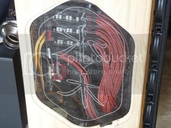
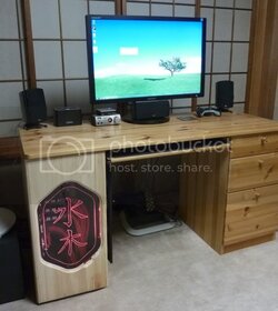
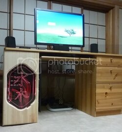
Alright, all fixed up and lighting wired in :) Enjoy the photos below, this is it for today!
newdoor14.jpg

newdoor15.jpg

newdoor16.jpg

newdoor17.jpg

newdoor18.jpg

newdoor19.jpg

newdoor20.jpg

newdoor21.jpg
 
Beautiful work miah! Sorry you had the little slip there but your side lighting turned out great, highlighting the etching perfectly. That's one pretty desk!
 
Back