• Welcome to Overclockers Forums! Join us to reply in threads, receive reduced ads, and to customize your site experience!

New build for a water chiller! 1/3Ton (1/2Ton TXV)

Overclockers is supported by our readers. When you click a link to make a purchase, we may earn a commission. Learn More.
Well here is the very start of the coil, I got lots of work don since, I built a suction line heat exchanger directly cupled to the coil to make it ultracompact
 

Attachments

  • Start of coil-with out shield.jpg
    Start of coil-with out shield.jpg
    71.3 KB · Views: 237
  • Start of coil-with shield.jpg
    Start of coil-with shield.jpg
    45.5 KB · Views: 235
  • Getting near finnished-1.jpg
    Getting near finnished-1.jpg
    31.8 KB · Views: 225
  • Getting near finnished-2.jpg
    Getting near finnished-2.jpg
    24.3 KB · Views: 220
  • Getting near finnished-3.jpg
    Getting near finnished-3.jpg
    22.8 KB · Views: 240
Last edited:
Yupp

I haven't calculated out the total volume of the coil yet,du to the fact I haven't designed the internal liquid handling system, till then I can't calculate how much total volume will be in there.
buuut to wildely wing it I'd say 2.67 Liters or so -0.212 (11 feet of 3/8ths)
So as is it will hold apx 2.458 Liters of water and the evap will hold 7.181 Onces of R-134a, and with the Liquid line sub cooler I aut to get a COP of APX 2.8 perhaps even 3? I'll have to run a simulation later to see it more accurately.

Sweet a cop of 4 way better then I thought.

With out the SLHX I loos quite a bit of my COP! down to 3.99 with out SLHX
 

Attachments

  • COP of 4 sweet.jpg
    COP of 4 sweet.jpg
    60.7 KB · Views: 423
Last edited:
Well a horrible thing happened a cold joint! so I bought a proper mapp torch and dam wish I had don it way sooner! thank fully I had enough space that I recovered and got the SLHX finished albeit not the way I originally intended,, but it will work with out having to remake a new one, and I developed a new method to make future ones better and faster :D so that was a plus.

Too dark to take any pics, but in the morning I will.
 
Fired it up and FROST tons of it, 10ounce R-134a so wonderfull, pics to follow tomorrow and here are the ones of the modified SLHX.
 

Attachments

  • New SLHX.jpg
    New SLHX.jpg
    119.9 KB · Views: 229
  • zoomed out view.jpg
    zoomed out view.jpg
    67.5 KB · Views: 217
  • Brazed joint.jpg
    Brazed joint.jpg
    56.9 KB · Views: 216
  • Home made AC Plant.jpg
    Home made AC Plant.jpg
    58.4 KB · Views: 225
hehe sure, do that when I take pics of the frozen every thing hehe, All this time was worth it, second the R-134a was put in it turned into a giant frost ball, and that means it is definitely moving heat! Just finished insulating the suction line as much I could, I still have to seal the pipes going through the cap, then install the liquid handling system then insulate the entire exchanger, I'll most likely do that with spray foam and that nice aluminized bubble wrap as the outer jacket.
 
well here are some non frosted pics as I am waiting for the PVC resin to fully cure but here are the pics as prommised.
 

Attachments

  • bulk head view.jpg
    bulk head view.jpg
    86.5 KB · Views: 207
  • bulk head view - slightly differant angle.jpg
    bulk head view - slightly differant angle.jpg
    54.8 KB · Views: 204
  • electricle box.jpg
    electricle box.jpg
    72.1 KB · Views: 199
  • F-D + LP.jpg
    F-D + LP.jpg
    111.7 KB · Views: 201
  • Full top view.jpg
    Full top view.jpg
    86.1 KB · Views: 438
Is that frosting all the way back to the compressor housing ;)
Overcharged just a tiny bit :p
Just playing with ya.. Good job :D :thup:
 
Well started to build the liquid end of it and rather p*ssed as I can't get the other fitting I need on the coast to make the second line, but here is the pic of the unit so far.

There is going to be a second barb put in when I get to a place that has them on this damned coast, and that is a stainless steel thermistor 6K at 21C and a 714 Op amp signal conditioner.

I'll be using a Delta-T for temp control system to lock it at -3.3 Evap.
 

Attachments

  • End cap-top view- with thermal sensore.jpg
    End cap-top view- with thermal sensore.jpg
    33.5 KB · Views: 214
  • Endcap -side view - with thermal sensore.jpg
    Endcap -side view - with thermal sensore.jpg
    31.3 KB · Views: 425
Well today I got a 1/2 NPT tap, this way I can simply screw in barbs and out if I want to change the size cost 25 bucks for it and damn, well worth it, makes life so much easier. I got the end sealed and got the barbs threaded in and just letting the PVC solvent to cure and kill off any remaining leaks then hook it up to the tap and see how well it holds a load!
 
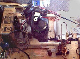
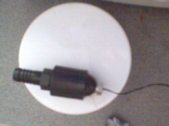
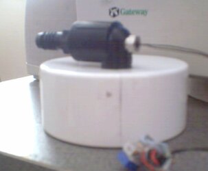
Well Just got me self an MCP600 from a gent,,, on this very forum; this will go in the liquid side of the system (Kinda goes with out saying lol).

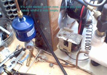
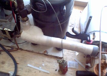
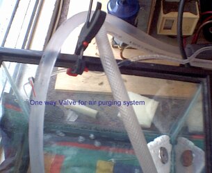
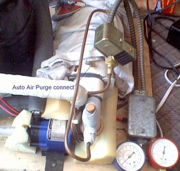
I may build in a res to the chiller cell hard piped as an air trap, or put in a purge valve to let it out manually during filling. There is a leak in the chiller cell that I'm trying to locate, so by filling it then locating the leak will be easy.

The next build will be a 6,000BTU/hr system again but much more well engineered. This current system more evolved then it was designed hence the very high cost of raw materials and the slow build, but it gave me a chance to re-sharpen my fabricating skills while I put into practise the stuff I have learnt in refrigeration. Another unique thing I'll do with the next build is the compressor will be water cooled its self via a small bleed off from the return water.

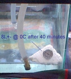
But for now the current project is on hold till the pump arrives, I may put the MCP600 to use in my current WC loop and take the MCP650 and put it to work in the chiller unit as noise will not be an issue there, and since the system designed operating temp is only -3.3C out 0C in there should be no issues with the temp at the pump due to its placement at the water return line.
 
Well I just found out a major problem with the chiller cell, the evap bulk head isn't sealing properly and the intake seal got cracked.

So now I have to figure a way to reseal the evap bulk head (I'm thinking 2 part epoxy this time) and figure a way to redo the unit inside that made the water go in a spiral, perhaps some 1/2 tube with a bunch of holes going at a 45degree angle?

Other then that I got the system rewired as planned and dam it's looking good with the conduit, not to mention starting much smoother with the new wiring (The old wire was 33 years old! and well worked, so nice healthy conducters seem to have made a world of differance to it!) I'll take a pic tommorow :)
 
Well pump has arrived and I located the two leaks

Leak 1 = End cap, PVC cement didn't seal all way round so added more and that got it

Leak 2 = Vacuum side bulk head seal failed (Broke open) so cut off the edges and am using silicon till I can figure out a better way that will with stand the torquing it'll experience till the res/chiller cell is insulated and bolted down.

As for pics sorry, one of the batts blew up so need to get some for the cam.

So far pump is mounted and I got some nice fibre re-inforced tubing and some insulation and installing that ordered some EL lights, blue and white, when a box is fabricated I think I'll do the entire trim with blue and snake the white through the indicating piping unit our some thing like that.

NOTE #2:
Well I was redoing the insulation I had to cut away to repair the leak in the bulk head I noticed the TXV bulb was sliping easily, so I figured I'd fix that while at it. I added some Ceramique and zap straps to tie it down, and well daAam, the thing tracks way better now BIG improvement.
 
Last edited:
got bateries! so here are the pics!

100% leak free and running smoothly!
 

Attachments

  • Therm + Intake.jpg
    Therm + Intake.jpg
    26.7 KB · Views: 204
  • Test load + Purge check valve.jpg
    Test load + Purge check valve.jpg
    85.5 KB · Views: 203
  • Chiller cell plus purge system.jpg
    Chiller cell plus purge system.jpg
    109.7 KB · Views: 204
  • Full plant view with water system.jpg
    Full plant view with water system.jpg
    80.3 KB · Views: 210
So.. when is it going to get to coolin a computer?
sounds like its about time for some screenshots :)
 
Back